0
\$\begingroup\$

Could someone please help me to calculate the output voltage across the voltmeter of a resistor divider network as shown in below schematic whose input can vary from -20V to +20V, R1 = 43K, R2 = 5.1K and Bias Voltage on R2 is 2.5V.
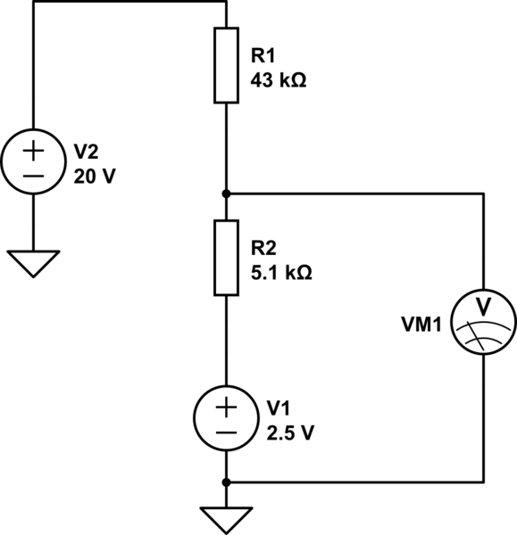
schematic

simulate this circuit – Schematic created using CircuitLab

\$\endgroup\$

2 Answers 2

1
\$\begingroup\$

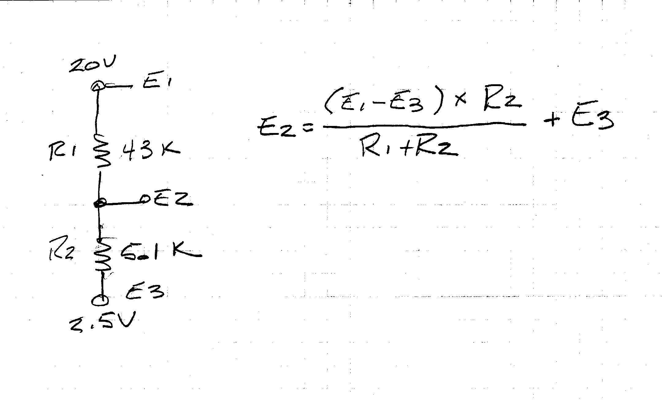
Handy formula, and it works a treat!

enter image description here

\$\endgroup\$
-1
\$\begingroup\$

Forget about VM1, If we simplified the circuit and connect two Voltage source of 20 V and 2.5 V, by connecting their GND, over all voltage should be 20V - 2.5V = 17.5 V, now two resistor in series, so over all current trough circuit is, I = V / R. where R = 43 + 5.1 = 48.1 kOhm, and V = 17.5 V so I = 17.5 V / 48.1 kOhm = 0.363825364 mA, Now as you can see, voltage drop across R2 is,

Voltage drop across V_R2 = R2 x I = 1.855509356 V and finally Volt Meter will read value Vm1 = V_R2 + V1 = 2.5 + 1.855509356 = 4.355509356 V

Is that clear?

\$\endgroup\$
2
  • 1
    \$\begingroup\$ He's looking for the general formula to cover V2 from -20 V to +20 V. You have only provided a specific answer at one input voltage. "k" for kilo. "K" is for kelvin. 9 decimal places on your calculations is probably a bit silly given practical resistor tolerances. \$\endgroup\$
    – Transistor
    Commented Mar 27, 2016 at 15:25
  • \$\begingroup\$ oh yes... i updated for that \$\endgroup\$ Commented Mar 27, 2016 at 15:54

Your Answer

By clicking “Post Your Answer”, you agree to our terms of service and acknowledge you have read our privacy policy.

Not the answer you're looking for? Browse other questions tagged or ask your own question.