0
\$\begingroup\$

I have been trying to grok the common base amplifier, and put together a few examples, but there is something that I do not get at all. I have the setup below. Things are working more or less as expected, but I measured the resistance of the bias divider, and even though I have a \$50k\$ and a \$100k\$ resistor, I measure \$\sim 33k\$ across both parts of the bias divider. Why does this happen?

I suspect that \$R_2\$, \$R_4\$, and the BE junction make up one part of a divider somehow and \$R_1\$, \$R_3\$, and the BC junction make up the other. Am I on the right track? How can I calculate these results reliably?

I should mention (since it's probably nearing finals time for students) that I am not a student.
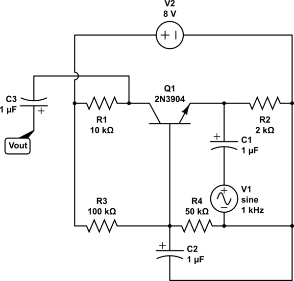
schematic

simulate this circuit – Schematic created using CircuitLab

\$\endgroup\$
7
  • 1
    \$\begingroup\$ You are going to have a lot of trouble if you don't follow why the \$50\:\text{k}\Omega\$ resistor and the \$100\:\text{k}\Omega\$ resistors set between two power rails make up \$50\:\text{k}\Omega\mid\mid 100\:\text{k}\Omega\approx 33.3\:\text{k}\Omega\$. That's a basic element you need to follow right away. Next is that the common base arrangement should, if oriented well for reading, look a lot like a CE arrangement except that the signal is removed from the input capacitor with that end of the capacitor then grounded, instead. \$\endgroup\$
    – jonk
    Commented Apr 23, 2019 at 21:22
  • 1
    \$\begingroup\$ Evidently it's been a long day. Clearly 50k || 100k = 33k. No clue what I was thinking there. \$\endgroup\$ Commented Apr 23, 2019 at 21:25
  • 1
    \$\begingroup\$ So, are you interested how the common base functions? You could examine this answer I wrote, earlier. I've oriented the schematic better, so it might make more sense. \$\endgroup\$
    – jonk
    Commented Apr 23, 2019 at 21:26
  • \$\begingroup\$ Well, yes. But here I thought something had gone mysteriously wrong because I was dumb and not thinking of the equiv value of the resistance in the divider for some reason. It's like if I had forgot how to add numbers while learning how to solve PDEs... \$\endgroup\$ Commented Apr 23, 2019 at 21:28
  • \$\begingroup\$ Well, read the above link I provided and see if it helps. \$\endgroup\$
    – jonk
    Commented Apr 23, 2019 at 21:29

1 Answer 1

1
\$\begingroup\$

schematic

simulate this circuit – Schematic created using CircuitLab

\$\endgroup\$
1
  • \$\begingroup\$ Thanks, I'll be accepting this to close the question. I know how dividers work, for some reason (lack of sleep?) I didn't recognize that the value should be 33k here... Sorry for the dumb question \$\endgroup\$ Commented Apr 23, 2019 at 21:27

Your Answer

By clicking “Post Your Answer”, you agree to our terms of service and acknowledge you have read our privacy policy.

Not the answer you're looking for? Browse other questions tagged or ask your own question.