-1
\$\begingroup\$

As we know, capacitors and inductors are most important components in circuit design.

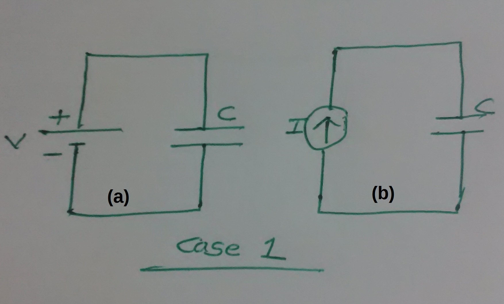
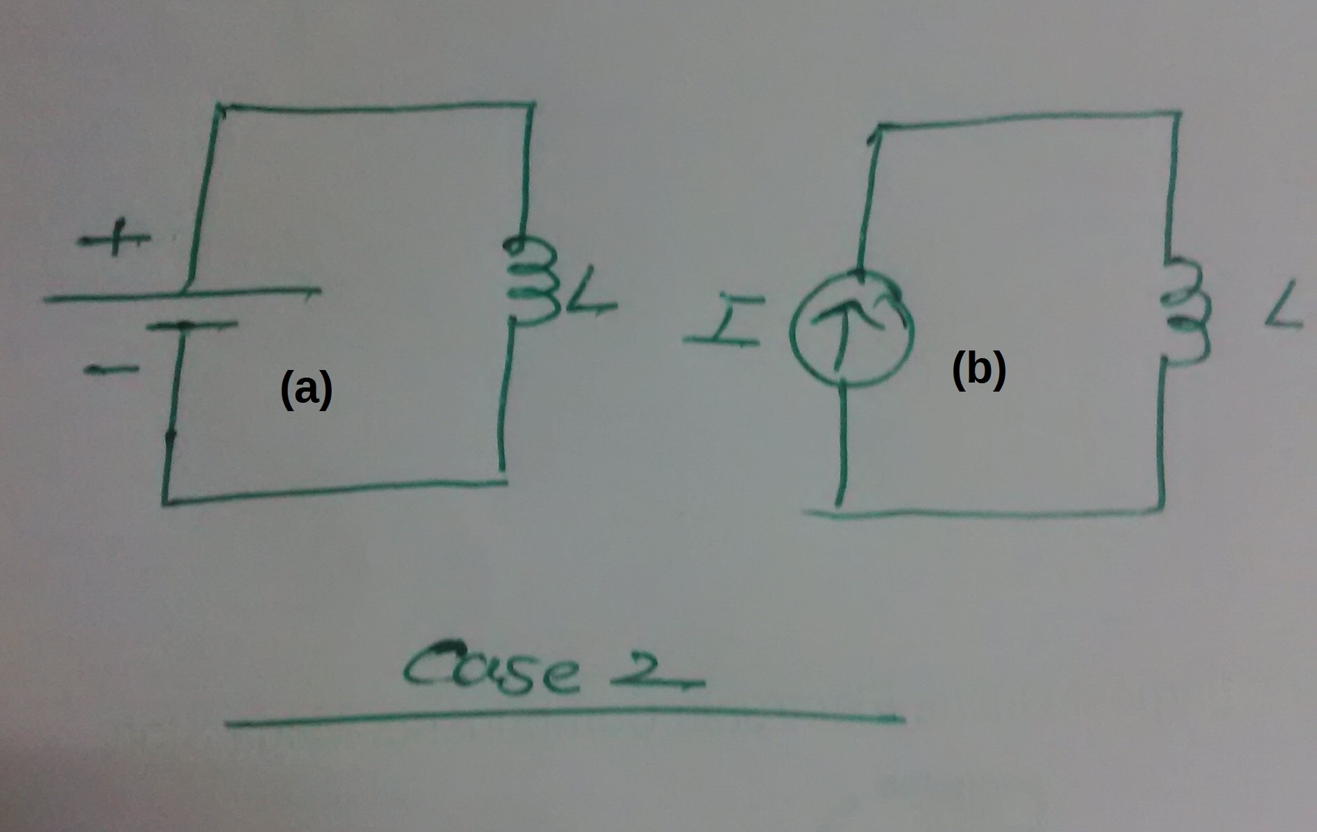
I am just curious about how they will behave when connected across voltage or current source as per below image and voltage and current wave-forms in each case.

PS: This can be tutorial question for most of the Electronics learner like us.

Capacitors Inductors

\$\endgroup\$
3
  • \$\begingroup\$ Should there be a switch in each circuit that closes at t=0, or should it be assumed the circuits have been closed for a long period? \$\endgroup\$
    – Chu
    Commented Apr 13, 2016 at 6:58
  • \$\begingroup\$ Yes. Wave-forms will be add on for understanding. :) \$\endgroup\$ Commented Apr 13, 2016 at 7:03
  • \$\begingroup\$ Any half-decent simulator could plot those for you. \$\endgroup\$ Commented Apr 13, 2016 at 7:54

3 Answers 3

2
\$\begingroup\$

There are only two formula that fully encapsulate the theory of inductors and capacitors in AC circuits and transient circuits. Understanding these formulas is more important than trying to ring-fence capacitor and inductor behavior by four trivial scenarios.

For an inductor \$V = L \dfrac{di}{dt}\$ or put another way...

If voltage is constant across an inductor, then \$\dfrac{di}{dt}\$ is constant.

This means current will ramp up to infinite amps unless current is limited.

For a capacitor \$I = C \dfrac{dv}{dt}\$ or put another way...

If current is constant through the capacitor, then \$\dfrac{dv}{dt}\$ is constant.

This means voltage will ramp up to infinity unless voltage is limited.

\$\endgroup\$
3
\$\begingroup\$

Case 1: voltage across C is V, current is 0. Case 2: voltage across L is 0, current is I.

With the assumption of ideal sources.

Derivation using the impedance: Z_C=1/(jwC), Z_L=jwL, where w in DC is 0 -> replace C with open circuit and L with short circuit.

\$\endgroup\$
2
\$\begingroup\$

1a: At \$\small t=0\$, I is an impulse of strength VC that charges the capacitor instantaneously to V. Thereafter, \$\small I=0\$.

1b: A constant current, I, flows from \$\small t=0\$; the voltage across C increases linearly with time (until the dielectric breaks-down).

2a: Current increases linearly with time (until something melts), satisfying \$ V=L\frac{di}{dt}\$ or \$ \frac{di}{dt}=\frac{V}{L}\$

2b: At \$\small t=0\$ a voltage impulse of strength \$\small IL\$ is generated (by induction), thereafter \$\small V=0\$ and a steady current, I, flows. Zero voltage is required from the current generator to support this current.

\$\endgroup\$

Your Answer

By clicking “Post Your Answer”, you agree to our terms of service and acknowledge you have read our privacy policy.

Not the answer you're looking for? Browse other questions tagged or ask your own question.