0
\$\begingroup\$

I have been learning about LC and LCR circuits.

My question is about inductors themselves, more specifically ideal inductors with zero resistance.

If I disconnect an ideal inductor from a DC supply, there should be very high voltage spike across the inductor as per \$V=L\frac{dI}{dt}\$.

How can this be? The two ends of the inductor are connected via zero resistance through the coil of the inductor itself and therefore wouldn't the voltage across the two ends of the inductor always be zero?

\$\endgroup\$
3
  • \$\begingroup\$ The ideal inductor would have series resiatance of 0 ohms. Based on your description you seem to think it is in parallel? \$\endgroup\$
    – Justme
    Commented Apr 3, 2022 at 11:37
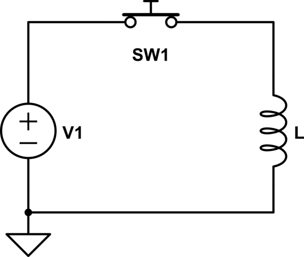
  • \$\begingroup\$ Apologies for not clarifying. I am invisioning a simple circuit with an DC supply, a switch and an inductor all in series. Then you open the switch and I am wondering wether there would be a voltage across the ideal inductor or not. \$\endgroup\$ Commented Apr 3, 2022 at 11:43
  • \$\begingroup\$ The voltage comes from the equation, V = L di/dt. If current is flowing in the inductor, and you disconnect it, then di/dt is infinite, so V will also be infinite. (of course it won't be infinite in a real inductor with a real supply, etc). If you want a physics answer, when current flows in the inductor, the inductor is storing potential energy in its magnetic field. That is the energy that is consumed in the process of making a voltage spike that arcs over whatever insulation you put in its path and dissipates by creating a plasma. \$\endgroup\$
    – user57037
    Commented Apr 3, 2022 at 15:30

8 Answers 8

8
\$\begingroup\$

The two ends of the inductor are connected via zero resistance through the coil of the inductor itself and therefore wouldn't the voltage across the two ends of the inductor always be zero?

You are assuming that an inductor obeys Ohm's law. It doesn't. Ohm's law is a law for resistors. An [ideal] inductor is not a resistor, therefore it doesn't obey Ohm's law (and neither does a voltage source, a capacitor, a diode, a transformer, or any other device that isn't a resistor).

The "law" that governs the operation of an inductor is

$$V = L\frac{dI}{dt}.$$

You need to analyze the operation of an inductor using this law rather than Ohm's law. And this law tells you that in order for the switch to open instantly, there must be an infinite (delta function) voltage impulse across the inductor.

This is a case that sometimes two "ideal" components in a circuit produces a logical contradiction, like two ideal voltage sources in parallel, or a switch connecting two ideal capacitors.

In this case you can't assume that both the inductor the switch are ideal and get a physically meaningful result in your analysis. You must consider either the arcing behavior of the switch, or the interwinding capacitance of the inductor (or both) to correctly model the circuit without singularities.

\$\endgroup\$
6
  • \$\begingroup\$ In any conductor \$\vec{J} = \sigma \vec{E}\$ -- the "microscopic" version of Ohm's Law. \$\vec{J}\$ being current density, \$\sigma\$ conductivity, and \$\vec{E}\$ the electric field. \$\endgroup\$ Commented Apr 3, 2022 at 16:16
  • \$\begingroup\$ @MathKeepsMeBusy, in the wires of an ideal inductor we can assume \$\sigma\$ approaches infinity, and so this relation is irrelevant to the question that was asked. \$\endgroup\$
    – The Photon
    Commented Apr 3, 2022 at 16:17
  • \$\begingroup\$ My comment applies to the section of your answer where you say "An inductor is not a resistor, therefore it doesn't obey Ohm's law" \$\endgroup\$ Commented Apr 3, 2022 at 16:29
  • 3
    \$\begingroup\$ @MathKeepsMeBusy, happier now? This is a circuit theory question. When we talk about inductors, we are talking about ideal inductors. If we want to model a real inductor with resistance and interwinding capacitance, we can include those parasitic elements as separate elements in our model. (And in any case, the resistive parasitic is still irrelevant to the question, being in series with the inductor...it's the parallel capacitive parasitic that will limit the inductor voltage in the real circuit, with the resistive parasitic only preventing the circuit from ringing forever). \$\endgroup\$
    – The Photon
    Commented Apr 3, 2022 at 16:32
  • \$\begingroup\$ Ohm's law still holds in all these cases if you consider the instantaneous impedance \$V=I\cdot Z(t)\$ \$\endgroup\$
    – tobalt
    Commented Jun 2, 2022 at 4:18
3
\$\begingroup\$

How can this be? The two ends of the inductor are connected via zero resistance through the coil of the inductor itself and therefore wouldn't the voltage across the two ends of the inductor always be zero?

An ideal inductor has zero resistance, but it has inductance.

there should be very high voltage spike across the inductor as per \$V=L\frac{dI}{dt}\$.

In a mathematical model of a circuit, inductance is defined by that equation. If you are analyzing a circuit that contains an inductor, you simply accept that that is how an inductor behaves.

Of course, there is a physical explanation of why a coil of wire exhibits inductance—of why the behavior of the coil is approximately described by that equation—but understanding it will take you deep into physics and math.

(see Wikipedia articles on Faraday's Law, and Lenz's Law, and on inductors in general.)

That's deeper than I can go, but the TLDR version is: When current flows in any conductor, the conductor is surrounded by a magnetic field. (The coils of conducting wire, and the ferromagnetic core in a practical inductor serve to concentrate that field.)

Anyway, that magnetic field stores energy. It takes energy to create the field (i.e., to ramp up the current), and the inductor returns that energy to the circuit when the field collapses (current ramping back down.) Those changes in energy are manifested as voltage that opposes the changing current, as described by the equation that you cited.

\$\endgroup\$
2
\$\begingroup\$

As long as there is variation in current, there will be a voltage \$V=L\frac{dI}{dt}\$ across an ideal inductor.

I think your misconseption is in "where" the "resistor" is in a non-ideal inductor: it has to be modelled in SERIES with the ideal inductor:

schematic

simulate this circuit – Schematic created using CircuitLab

So if the internal resistor (r) tends toward 0 (i.e. ideal inductor), then it is NOT shorting the terminals of the ideal inductor.

Now, why can we model the inductor as an ideal inductor as one end and a resistor at the other end?

Let's suppose we cut the inductor into N small (identical) inductors with resistance r/N, and inductance L/N, we get:

schematic

simulate this circuit

As the same current passing through each component is the same, you can reoder the components while keeping the same voltage between A and B.

schematic

simulate this circuit

Now, as resistors add in series, the total resistance is Rtot=N*(r/N)=r. Similarly, inductors also add in series, so Ltot=N*(L/N)=L.

EDIT: with your new comment, about the specif case of a DC circuit with only ideal inductor and switch.

schematic

simulate this circuit

If there is no internal resistor neither in the inductor, nor in the wires, nor in the supply, nor in the switch (ie all components are ideal), then you get a short circuit when the switch is closed. It means your voltage source provides infinite current (and therefore power).

Now let’s supose the voltage source somehow limits current (for example with an internal resistance). We get some current accross the inductor. When we open the switch:

  • if it is non ideal, we will probably get some electric arc, dissipating the energy stored in the inductor.
  • if it is ideal and doesn't create an arc, then there might be some other non ideal element able to slow down the variation of voltage (for example some parasit capacitance).
  • if you deny also those non-idealities, then you get infinite voltage across your inductor (and then, it makes no sens to continue considering that all is ideal, because with infinite voltage, you create electric arcs or destroy something).
\$\endgroup\$
5
  • \$\begingroup\$ This response was very helpful and clear, thank you. I am just not understanding how a voltage can be created across the ideal inductor in the circuit you have drawn. If we label point A as the point directly above the inductor and point B as the point directly below the inductor, then points A and B are electrically common since there is zero resistance between them. Hence when we open the switch, points A and B are still electrically common and the voltage between them should be zero? I'm just trying to understand it with my basic knowledge and ohm's law V=IR and R=0, so V=0? \$\endgroup\$ Commented Apr 3, 2022 at 12:19
  • \$\begingroup\$ "It means your voltage source provides infinite current" is not true, if the switch is only closed for a finite period of time. The inductor ensures the current only increases at a finite rate, and therefore can't become infinite unless the switch remains closed for an infinite time. \$\endgroup\$
    – The Photon
    Commented Apr 3, 2022 at 15:14
  • \$\begingroup\$ @ThePhoton : indeed, the reasonning of infinite current is only true for "DC", which indeed means infinite time. However, even for a finite time, V=Ldi/dt, so I=V/L * t, which quickly becomes very big (big enough that no reasonnable power supply can prowide that much power). Even if taking the biggest inductor available on digikey (150H), and a 5V supply, one reachs 2A in 1 minute, and 120A in 1h. For a "normal" inductor (for example 1mH, it's 5000A after 1 second. After 10 hours, we would get 180 000 000 A, or nearly 1GW, the power of a nuclear plant! \$\endgroup\$
    – Sandro
    Commented Apr 3, 2022 at 19:50
  • \$\begingroup\$ @SwissGnome : I think that your misunerstanding comes from the fact that ohms law ONLY applies to resistors : for an (ideal) resistor, V=IR. For anything that is not a resistor, the eqution is different. For an ideal inductor, V=L di/dt instead. Or for an ideal wire, V=0. Or for a capacitor, I=CdV/dt, ... NB : there is a generalization of "ohms law" for other linear components such as capacitors and inductors, but it requires to use complex numbers and applies only for periodic signals (period w). You then have (in complex) : U=Z*I,where Z=R for a resisor, Z=jLw for an inductor, \$\endgroup\$
    – Sandro
    Commented Apr 3, 2022 at 19:57
  • \$\begingroup\$ J=1/(jCw) for a capacitor. Those complex numbers Z are called impedance, and are added in series (and there inverses are added in parallel). For your "real" inductor, you sum the impedance of the resistor and the ideal inductor, so you get Z=R + jLw. Even if you set R to 0, you don't have Z=0 \$\endgroup\$
    – Sandro
    Commented Apr 3, 2022 at 20:00
1
\$\begingroup\$

Often, for practical purposes, we do not draw a distinction between a voltage drop through a component and an electromotive force generated through that component. Both are measured in volts. However, sometimes the distinction needs to be drawn in order to avoid running into apparent paradoxes.

The voltage drop through a component is the line integral of the electric field through that component.

$$U = \int_a^b \vec{E} \cdot d\vec{s}$$

The emf generated by an inductor is the line integral of the rotational component of the electric field through that component.

$$\mathscr{E} = \int_a^b \vec{E}_{rot} \cdot d\vec{s}$$

According to Kirchhoff's Voltage Law, around any loop, the sum of the EMFs through the components in the loop equals the sum of the voltage drops through the components of the loop.

$$\sum_i \mathscr{E}_i = \sum_i U_i$$

Or in Kirchhoff's original presentation

$$\sum_i \mathscr{E}_i = \sum_i I_iR_i$$

where \$I_i\$ is the current through a component, and \$R_i\$ is the resistance offered to that current by that component.

You are correct that the voltage drop, as defined above, through an inductor depends upon the resistance of the wire and the current through it.

The two ends of the inductor are connected via zero resistance through the coil of the inductor itself and therefore wouldn't the voltage across the two ends of the inductor always be zero?

For an ideal inductor, where the resistance is 0, the voltage drop across it will be 0. However, the EMF generated by an inductor will result in a voltage drop across resistances that are connected to the inductor in a circuit loop. Thus, if you connect a volt-meter across the terminals of an inductor (experiencing changing current), a voltage drop will be present across the volt-meter, and hence the volt-meter will give a reading proportional to the EMF generated by the inductor, rather than the voltage drop through the inductor. In a sense, the EMF causes a voltage drop elsewhere in the circuit.

\$\endgroup\$
1
\$\begingroup\$

The two ends of an ideal inductor are connected by a zero resistance wire. However, to make this an inductor, this wire encloses a loop of some area.

When a current flows round this loop of wire, a magnetic field is set up in the area defined by loop.

When the magnetic field in the area of the loop is changed, then a voltage is generated round the loop. This voltage appears across the ends of the wire.

We observe this to be so, experimentally. Why it happens depends on your definition of 'why'. You could explain it in terms of other deeper theories, quantum electro dynamics (QED) for instance is probably the deepest, or a little higher using Maxwell's equations. However, ultimately, you could say 'why' to these theories as well. Don't forget that both of these theories were developed to summarise the experimental results we observe.

To answer your question of 'How can this be that the two ends of a zero resistance wire generate a voltage between them when the current changes?' It happens. That's the observed reality. Deal with it.

\$\endgroup\$
1
\$\begingroup\$

There are two ways to view this: an inductor with resistance obeys the equation \$U = R\cdot I + L\cdot\frac{\mathrm d\,I}{\mathrm d\,t}\$. With zero resistance, the left term is zero, but the right term is still there.

The other way to look at it is by considering Kirchhoff's equations that state the total voltage in each loop of a circuit is zero: the amended version is that the total is not zero but adds up to the (negative) time derivative of the flux change through the loop. An inductor has a multiplicity of loops around the relevant flux, and it is also responsible for creating the flux in the first place via magnetisation of its core (or of air/vacuum) according to its permeability.

With either of those views, you need to take into account what makes the inductor an inductor (namely tying its current to a significant magnetisation and its voltage to the temporal change of the related significant magnetic flux). When stipulating an ideal inductor without resistance, no voltage is due to material's electric conductivity, but that does not take care of the coupled magnetic fields and the voltages induced by their change.

\$\endgroup\$
1
  • \$\begingroup\$ Kirchhoff's Voltage Law (per Kirchhoff himself) is that the sum of the voltage drops around a loop is equal to the EMF around the loop. Books have commonly dropped this EMF term giving an equation that only works when there is no inductively induced EMF. But Kirchhoff's law, per Kirchhoff himself, is actually correct and is in agreement with Faraday's Law. \$\endgroup\$ Commented May 13 at 13:35
0
\$\begingroup\$

It does not matter if the inductor is ideal or not. And ideal inductor just has inductance, it does not have any series resistance. A changing magnetic field induces a voltage in any inductor. If current to inductor is suddenly turned off, the rate of change of current di/dt is infinite so induced voltage is also infinine.

\$\endgroup\$
0
\$\begingroup\$

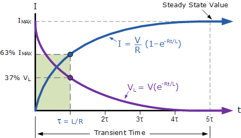
enter image description here

(Image source: Electronics Tutorials - Transient Curves for an LR Series Circuit)

Referencing the picture:
As R goes to 0 and time goes to infinity the exponential term approaches 0.
I = V/0 > infinity
VL = V x 0 = 0

No R
DC V, infinite bus
Your system is undefinable.
This thought model will not help you understand L in a circuit.

The time constant is L/R = infinite meaning the time must go to 0, or instantaneous.

Close switch: I goes instantaneously to infinity, V/0
There will be no V across L

Open switch: I goes to 0 instantly

Since I is unbounded it's derivative is also, but we know V = 1, not possible.

The energy is infinite also
E = 1/2 L I^2

\$\endgroup\$

Your Answer

By clicking “Post Your Answer”, you agree to our terms of service and acknowledge you have read our privacy policy.

Not the answer you're looking for? Browse other questions tagged or ask your own question.