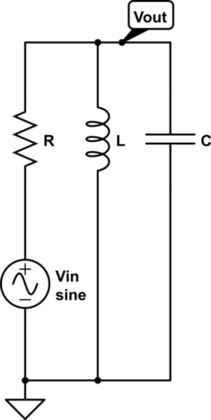
I'm trying to induce Quality factor of RLC circuit.
In series, I did it with Frequency responce $$ H(s) = R/(R+sL+1/sC) = (something)/(s^2+2sw_0\zeta+w_0^2)$$ And $$Q=1/2\zeta$$ But I can't find how to induce it in parallel.
If you did the math you would find that the \$2\zeta\omega_0\$ term comes out as \$\frac{1}{CR}\$.
Knowing that \$\omega_0 = \frac{1}{\sqrt{LC}}\$ you can compute zeta as equal to \$\frac{1}{2R}\sqrt{\frac{L}{C}}\$.
You know how to turn zeta into Q so no need to restate that.
Explanation
You have to imagine driving the parallel RLC from a current source because a current source has infinite output impedance and therefore its impedance doesn't alter the circuit values. Next you turn the current source and the parallel resistance of the RLC into a voltage source and series resistor. Again, I stress no impedances or math is harmed in this re-arrangement!
You then can make a sensible TF of the new circuit: -

simulate this circuit – Schematic created using CircuitLab
\$H(s) = \dfrac{X_L||X_C}{R + X_L||X_C}\$
Where \$X_L||X_C = \dfrac{\frac{sL}{sC}}{sL + 1/sC} = \dfrac{sL}{1+s^2LC}\$
Stuff it in the formula and you get: -
\$H(s) = \dfrac{sL}{R + s^2LCR + sL}\$
Next, divide through by LCR to get: -
\$H(s) = \dfrac{\frac{s}{CR}}{s^2 + \frac{s}{CR} + \frac{1}{LC}}\$
Now it's in standard form for recognizing that \$\frac{1}{CR} = 2\zeta\omega_0\$. Continue to find zeta as per my original answer.
How did you derive the transfer function for the series circuit? Answer: Complex voltage divider. Why didn`t you try this method also for the parallel combination? Then, if you manipulate the resulting function with the aim to have again a quadratic polynominal in the denominator you can identify the wanted parameter.
\$to start and end inline math. \$\endgroup\$\$\sqrt{L/R}\$, for example, to get a square root symbol (\$\sqrt{L/R}\$). \$\endgroup\$