For the past few weeks I've been trying to understand Field-oriented-control for 3-phase motors. Eventually I would like to implement one. I've gone through dozens of application notes from Microchip, Atmel, TI and ST. Unfortunately I'm having some trouble understanding the phase current measurement requirements.
As you know for FOC we need to know all 3 phase currents (lets call them I_A, I_B and I_C). Since according to Kirchhoff’s law (I_A + I_B + I_C = 0) we can get away with measuring just 2 phase currents and calculating the remaining one. Most application notes use 2 low side current shunt resistors to measure the phase current I_A and I_B.
My question is that every application note that I've seen states that it is important to be able to measure the voltage difference across the shunt resistor both as a positive and negative value (I assume because the current in the each phase can have two directions). To do this they recommend to add a 1.65V offset to the current measuring op-amp (assuming a 0-3.3V ADC range).
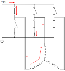
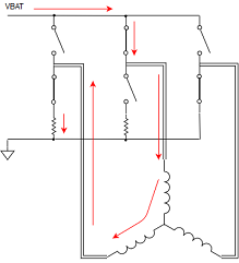
However when I try to visualize the current path in the 3-phase inverter I only see current flowing through the shunt resistor in one direction. Please look at the images I made to illustrate my point.
As you can see, regardless of the phase current direction, the current flowing through the shunt resistor is the same. We can then infer the direction of the phase current by looking at the inverter configuration at that that particular sampling instant.
Furthermore, I've only seen low side current measurement in FOC application. Recently I came across the BTN8982 half-bridge IC from Infineon. This device includes a high side current mirror (which outputs a current proportional to the current through high side mosfet). As such it can only sense currents uni-directionally. Can this device be used for FOC applications?
Thank you!


