0
\$\begingroup\$

I am trying to verify voltage drop across a resistor as seen on my multimeter with basic ohms law calculations.

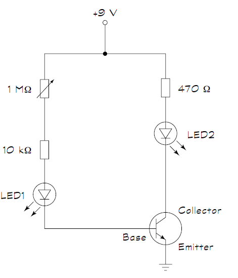
As shown in below circuit (from Electronics for DUMMIES). The multimeter shows a voltage drop of 6V at 1M ohm resistor. However that is not what my math shows and I think something is wrong with my maths. Here is how I am doing it

Vb=9V
First Find total Resistance of circuit
R1=1 M ohms= 1000000 ohms
R2=10 k ohms = 10000ohms
R3=470 ohms


R1 and R2 are in series with each other but both combined are in parallel to R3, so
Rtotal = (R1+R2)||R3 = (1000000+10000)||470
= 1010000 || 470
= (1010000 x 470)/(1010000 + 470)
=474700000/1010470
=469.7813888586499=469.7

Now to find Total Current
I=9V/469.7ohms
= 0.019 Amps

Voltage drop across  R1(1 M ohms)
V1=0.019 x 1000000 = 19000(This cant be right)

Did I miss anything?

enter image description here

The NPN transistor is BC546B, which is acting as an amplifier

\$\endgroup\$
3
  • 1
    \$\begingroup\$ Did you take into account the meter has a resistance value which effects the voltage drop across the 1M0 by lowering the overall resistance (gives a lower reading)? \$\endgroup\$ Commented Apr 22, 2016 at 19:03
  • \$\begingroup\$ Ditto and how about telling us what R1, 2 and 3 are in your circuit. Also how are R1 + R2 in parallel with R3? \$\endgroup\$
    – Andy aka
    Commented Apr 22, 2016 at 19:05
  • \$\begingroup\$ yea I did, but still the calculation seems way off \$\endgroup\$
    – user482963
    Commented Apr 23, 2016 at 7:58

1 Answer 1

1
\$\begingroup\$

This is not a parallel connection, because the transistor's base and collector are not at the same voltage. As a general rule of thumb, NPN transistor common-emitter amplifier like this will have Vbe about 0.6v or 0.7v. Since emitter is grounded, assume Vb is 0.6v. You can also assume that the LED has a somewhat constant voltage when lit, about 1.5V for Red LED if I remebver correcfly. Now you have an estimate for the voltage across the series resistors. Use that to estimate the current through the left branch, which is the transistor's base current. Now you can calculate the collector current by multiplying the base current by the transistor's current gain (beta) from the datasheet. Finally, the collector current lets you determine the voltage drop in the 470ohm resistor, and you can again assume roughly constant LED voltage when lit.

Measuring a 1Mohm resistor is not trivial. The measurement is affected by the measurement system. Your voltmeter is not shown in the circuit, but it will look like another high resistance in paralell with whatever you're measuring. If the voltmeter input is 10Mohm equivalent, and you connect it across a 1Mohm resistor, you're really measuring 10M in paralell with 1M. At some point the input resistance can be cinsidered negligible, but 1Mohm may be too close to the input resistance. Your voltmeter should have a datasheet or manual, that will list the equivalent input resistance of the volts measurement.

Also note that you can measure voltage while the circuit is powered on, but you cannot directly measure ohms of a resistor that is part of a circuit. The DMM ohms range can be used when sorting individual resistors before connecting them into a curcuit. DMM ohms measurement actually drives a test current through the resistor and measures the resulting voltage drop; this will not work right if there is already an operational current flowing.

\$\endgroup\$
1
  • \$\begingroup\$ thank you for the detailed response, so you are suggesting that to calculate voltage drop across components in both branches, I should treat both branches separately and calculate their total resistances separately ? \$\endgroup\$
    – user482963
    Commented Apr 23, 2016 at 7:57

Your Answer

By clicking “Post Your Answer”, you agree to our terms of service and acknowledge you have read our privacy policy.

Not the answer you're looking for? Browse other questions tagged or ask your own question.