0
\$\begingroup\$

Schematic

schematic

simulate this circuit – Schematic created using CircuitLab

I am a newbie in electronics and I am trying to drive an LED with a series resistor from a 3.3V microcontroller. The max strength of my microcontroller is 6mA and I have purchased an LED that has a forward current of 5mA and forward voltage of 2.9V (SMLE13BC8T from element14).

LED Datasheet - http://www.farnell.com/datasheets/2291105.pdf?_ga=2.248677317.314538259.1522008542-1628637695.1510818085&_gac=1.187272666.1519702428.CjwKCAiA_c7UBRAjEiwApCZi8b1AXd13x8uo1jKdDvDSS0hVLYvivMQv_-U7Wa3ZxPwHUqg1C72JOhoCITMQAvD_BwE

I did the resistor calculation and found that a 100 ohm resistor will be able to drop my voltage to a usable range for LED. Before testing this on the actual microcontroller I tried the LED - resistor combination by supplying 3.3V and found that the LED is super bright and heats up in few minutes usage. Hence I measured the current across my circuit using a multimeter and found that it is 71.6mA. I tried to increase my resistance to 200 ohms and the LED did not glow. Can someone help me to solve this. Am I using a wrong LED ?

I did search the forum for similar issues and did not find the answer, hence please don't close this as duplicate.

\$\endgroup\$
7
  • 1
    \$\begingroup\$ I suspect that your resistors are not the values you think they are. The "100 Ohm" resistor must be well under 10 Ohms to give 71 mA. \$\endgroup\$ Commented Mar 26, 2018 at 18:22
  • 2
    \$\begingroup\$ Your numbers don't add up. 70mA thru a 100R resistor means you must have had 7V across the resistor. Draw us a schematic (edit your question and use the built-in schematic tool) and show us what you've connected where (including how & where you measured). \$\endgroup\$
    – brhans
    Commented Mar 26, 2018 at 18:23
  • 2
    \$\begingroup\$ Did you measure the current by putting the multimeter probes across the resistor rather than in series? \$\endgroup\$ Commented Mar 26, 2018 at 18:29
  • \$\begingroup\$ I have rechecked my resistor and it is 100 Ohm itself, and the multimeter is connected in series with the circuit. Please find the schematic attached. \$\endgroup\$
    – Zac
    Commented Mar 26, 2018 at 18:41
  • \$\begingroup\$ Can you repeat your bright glowing experiment with alleged "100 Ohm" resistor? \$\endgroup\$ Commented Mar 26, 2018 at 18:52

2 Answers 2

0
\$\begingroup\$

No, you are using a perfectly right LED. Modern high-intensity LEDs are very efficient devices, and are pretty bright even with 1-2 mA of current. Apparently you misread the value of resistor, it could be 10 Ohms or even 1 Ohm to get the current you experienced. Or you connected your Ampermeter to the wrong end of the resistor. If you tried your LED from 3.3V supply with 200 Ohm resistor and it doesn't glow, it means that you fried the LED in your previous experiment (since it was already too hot).

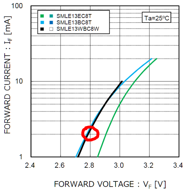
With 200 Ohm in series and 3.3V source the working point should settle at about 2.9V per specifications, which means that the current across 200 Ohm (0.4 V drop) is about 2 mA. From specifications: enter image description here

So you need to re-check your experimental setup, voltages, connections, etc.

The standard way is to connect the LED as you suggested, with any resistor from 50 Ohm to 3-4 kOhm in series, depending on the brightness you feel comfortable with. Keep in mind that your MCU GPIO will have about 50 Ohms of internal impedance (given the 6 mA default configuration). Even when connected to a GPIO directly, nothing dramatic should happen.

\$\endgroup\$
7
  • \$\begingroup\$ Thanks Ali, your calculations seems to be correct. I tried this with a usual 20mA white LED and just connecting 100 Ohm itself dropped the current to 4.1 mA and with 200 Ohm it was only consuming 2.1mA. \$\endgroup\$
    – Zac
    Commented Mar 26, 2018 at 19:11
  • 1
    \$\begingroup\$ Keep in mind, that for accurate readings of currents in low-voltage circuits the DMMs (in ammeter mode) introduce some voltage drop (called "burden voltage", a voltage across internal shunt resistor), which might affect results. \$\endgroup\$ Commented Mar 26, 2018 at 19:30
  • \$\begingroup\$ Appreciate that Ali. Should I consider using 200 Ohms (my calculation led me to choose 100 Ohms) to be on the safer side ? 200 Ohms itself is giving sufficient brightness \$\endgroup\$
    – Zac
    Commented Mar 26, 2018 at 19:36
  • \$\begingroup\$ A consideration with GPIO's is between active hi or lo drive. Many micro pins have lower on-resistance driving low (the designer makes the output P and N fets the same size, but N fets have lower R for the same area) \$\endgroup\$
    – Henry Crun
    Commented Mar 26, 2018 at 19:43
  • \$\begingroup\$ @Zacson, everything is technically "safe", even no resistor. The definition of "6 mA drive" , if used to drive LOW, is that the GPIO will deliver some minimal voltage level (usually 0.4V) at specified current. This means that in LOW state the driver will have 66 Ohms and voltage will be at 0.4V, so 2.9V will be left for the LED. But the LED will likely be bright as hell. I am typically using 1k-2k, up to 4k on InGaN green LEDs when I feel them as being too bright. \$\endgroup\$ Commented Mar 26, 2018 at 19:59
0
\$\begingroup\$

I think I found out the issue. My LED and resistor was already soldered into my microcontroller board (even though the MCU was not powered up) and somehow the resistance across my LED is showing as 300 Ohms while it is placed on the board. Hence it took more current to light up the LED. I have now taken out the LED from the MCU and everything seems to be fine.

\$\endgroup\$
3
  • \$\begingroup\$ As an aside, this is exactly what happens inside leds, as your cheap led strips start to fail and some of the individual leds go dimmer than the others. The led develops leakage R across the junction that bypasses the led. \$\endgroup\$
    – Henry Crun
    Commented Mar 26, 2018 at 19:46
  • 1
    \$\begingroup\$ Then the circuit in the original question is misleading, there must be other connections. Please be aware that GPIOs on all MCUs have clamp diodes attached to power and ground rails (ESD protection), internally. So even when MCU is not powered, GPIO might provide a substantial current path via these diodes into system rails. What you did was a really "unsafe" experiment. \$\endgroup\$ Commented Mar 26, 2018 at 20:33
  • \$\begingroup\$ Resistance measurements of components in a circuit can be very misleading - the ohmmeter reads the total effective resistance between its leads, which may involve other components and current paths besides the one you see between your probes. \$\endgroup\$ Commented Mar 26, 2018 at 22:36

Your Answer

By clicking “Post Your Answer”, you agree to our terms of service and acknowledge you have read our privacy policy.

Not the answer you're looking for? Browse other questions tagged or ask your own question.