0
\$\begingroup\$

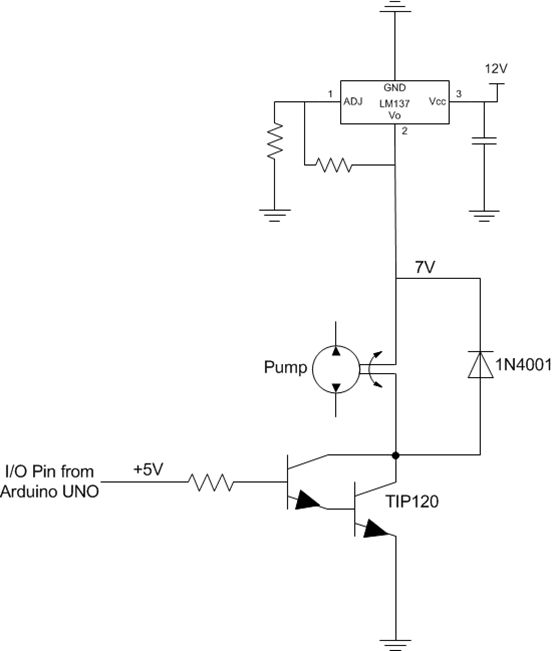
enter image description here

So I know lots of people have asked this question but the more answers/threads I read the more confused I get because people explain it so differently.

My confusion is why do I have to even use the hFE Current Gain in any part of my calculation for the base resistor value?

My thought process is since Vbe is 1.4V (0.7*2 transistors) and my arduino output is 5V then lets say "I choose" to have Ib be 2mA then by ohms law R=(5-1.4)/2mA=1.8K ohms.

Does this thought process not work? The purpose of the resistor is to limit current to the transistor, well if I decide to limit it to 2mA then I have all my parameters to choose R without having to use hFE at all.

\$\endgroup\$
11
  • 1
    \$\begingroup\$ Why would you choose 2mA? \$\endgroup\$ Commented Apr 27, 2016 at 22:03
  • \$\begingroup\$ Ditch the Darlington, use a MOSFET. \$\endgroup\$
    – Matt Young
    Commented Apr 27, 2016 at 22:06
  • \$\begingroup\$ @IgnacioVazquez-Abrams no special reason. Just to get a R value. I could choose 3mA, 4mA, 5mA etc. the goal is to get a resistor value. \$\endgroup\$
    – Suh Dude
    Commented Apr 27, 2016 at 22:09
  • \$\begingroup\$ "No special reason" is silly. That's not engineering, that's Arduino-novice-level guessing. \$\endgroup\$ Commented Apr 27, 2016 at 22:11
  • \$\begingroup\$ @IgnacioVazquez-Abrams I agree but that's why I'm asking how come people always use hFE when calculating that R value? Okay so how instead of No Special reason I say that the max current output of the arduino uno pin is 40mA and obviously that's max rating. So something considerably lower will be safer so how about 5 mA. \$\endgroup\$
    – Suh Dude
    Commented Apr 27, 2016 at 22:14

4 Answers 4

1
\$\begingroup\$

You are, in one respect, correct in not trusting hfe, but not for the reason you think.

hfe is specified for a certain voltage and current. For the TIP120, this is a Vce of 3 volts. Problem is, you don't want to run your transistor at 3 volts. You want the transistor to be in saturation, with Vce as small as possible.

Looking at saturation numbers, you'll see a specified base current and collector current. As a good rule of thumb, use the closest numbers to your application. Then, you can compute your base resistor as you suggest.

When using single transistors, the general rule is to assume an hfe of 10 to drive the transistor into saturation. This is not a hard and fast rule, but it will consistently give solid performance and low saturation voltages.

\$\endgroup\$
4
  • \$\begingroup\$ Still trying to get a grasp of transistors and its terminology. So we want Vce to be as small as possible because we don't want a big voltage drop across our transistor correct? And in order to put a transistor into saturation we have to apply enough voltage at the base? \$\endgroup\$
    – Suh Dude
    Commented Apr 27, 2016 at 23:16
  • \$\begingroup\$ @TylerRobles: Perfect! \$\endgroup\$
    – EM Fields
    Commented Apr 28, 2016 at 0:26
  • \$\begingroup\$ @TylerRobles - Well, almost perfect. For BJTs (bipolar junction transistors - that is, not MOSFETs) what you need to supply is base current, rather than voltage. But it's generally easier to control voltage and resistance, so that's how you do it. \$\endgroup\$ Commented Apr 28, 2016 at 2:15
  • \$\begingroup\$ Quote: "what you need to supply is base current, rather than voltage". Rather than voltage? Really? Didn`t you recognize in the past several discussions (partly polemic disputs) about the question: voltage vs. current control for BJTs? \$\endgroup\$
    – LvW
    Commented Apr 28, 2016 at 8:20
1
\$\begingroup\$

The TIP120 incorporates two base-emitter resistors (120 ohms and 8K), which minimize leakage, but reduce the effective hFE (and, more importantly here, give it a kind of threshold that is relatively high compared to an ordinary darlington).

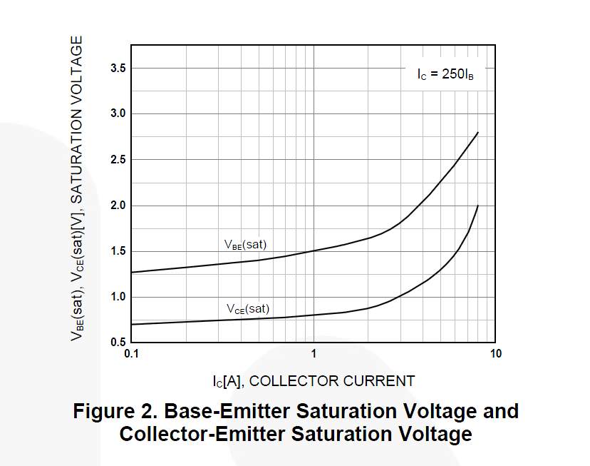
Figure 2 in the datasheet shows typical Vce with Ic/Ib = 250, as does the guaranteed Vce(sat) numbers in the datasheet - (both guaranteed numbers are Ic/Ib = 250) so I would suggest that as a useful guideline.

enter image description here enter image description here

You will get almost no improvement in Vce(sat) numbers by going for more than 1/250 of the collector current, and you may get significantly worse if you go much less, so it's safest to go with 1/250 in the 1A-3A 'wheelhouse' of this part (here is the only place the hFE curve Fig 1 comes in handy), perhaps a bit more at higher or lower currents. That's probably close enough unless you need to operate at low temperatures where hFE will drop.

So, at 1A out you need about 4mA base current. The microcontroller output won't be quite 5V when supplying 4mA, so if you use (4V-1.5V)/0.004 = 625 ohms (pick the next lowest E24 value 620 ohms) and you should be fine. Note that the 1.5V is the typical value from the graph in Fig 2 above, I didn't calculate it. The worst case value is 2.5V at 3A current (vs. 1.7 typically)- using that would be more conservative again, but it gets you down into the 330 ohm range and is probably unnecessary for an ordinary design.

\$\endgroup\$
6
  • \$\begingroup\$ that helps a lot thank you! The theory makes a little more sense now based on your explanation. One question is how come the Arduino wont be 5V just from supplying 4mA? Can you explain how you know. \$\endgroup\$
    – Suh Dude
    Commented Apr 28, 2016 at 19:20
  • \$\begingroup\$ It's an educated guess, and being a guess, it's on the conservative side (especially considering the relatively high source current capability of the Atmega series). The regulator could be low by 5-10%, depending on the type, and the output will drop a bit- typically about 0.1V at 4mA and maximum maybe 0.15 or 0.2V, so total maybe 4.3V rather than 4.0V. It's worse at high temperature, but Vbe drops and hFE increases so I wouldn't necessarily take that into account. \$\endgroup\$ Commented Apr 28, 2016 at 21:09
  • \$\begingroup\$ I guess the question is more of WHY does it drop once you try to drive something on the I/O pin. Like the theory. \$\endgroup\$
    – Suh Dude
    Commented Apr 28, 2016 at 21:57
  • \$\begingroup\$ Oh, inside there is a P-channel MOSFET pulling it towards whatever the Vdd is (nominally 5V). It will have a bit of resistance so the voltage never will be quite 5V. Some micros have more than others especially at low supply voltage. See Figure 31-24 and the top line of Table 30-1 in the datasheet \$\endgroup\$ Commented Apr 28, 2016 at 22:12
  • \$\begingroup\$ Perfect. Didn't know there was a mosfet near the output of the pin inside the arduino, makes sense that it would have voltage drop so the output wouldn't be exactly 5V. You would think they would of designed the Vdd to be like 5.3 so that it would take into account the 0.3V drop so we can get exactly 5V. \$\endgroup\$
    – Suh Dude
    Commented Apr 28, 2016 at 22:22
0
\$\begingroup\$

Transistors are current controlled devices that is Ic=Ib*Hfe so to give the right value to base resistor you should start from current required by pump so you will know Ic. From Ic you could define Ic= 10*Ib for giving minimum Vce drop at saturation, but with darlingtons probably you could use Ic=100*Ib. Anyway mosfet are better switches in these applications because voltage drop is much less.

\$\endgroup\$
8
  • \$\begingroup\$ I just don't know what Hfe to use from the datasheet. My pump draws about 900mA \$\endgroup\$
    – Suh Dude
    Commented Apr 27, 2016 at 23:44
  • \$\begingroup\$ From this datasheet :fairchildsemi.com/datasheets/TI/TIP120.pdf on figure 2 you can see that Hfe is about 250 at 1 A so you can find the right value for base resistor because 4 mA of base current are required. \$\endgroup\$
    – krufra
    Commented Apr 27, 2016 at 23:50
  • \$\begingroup\$ So Ic=250*Ib and Ic is 1A from the pump so 1/250=4mA? You are just using the little equation at the top of the graph right? \$\endgroup\$
    – Suh Dude
    Commented Apr 27, 2016 at 23:55
  • \$\begingroup\$ Yes the plot is done with iC= 250*iB if you give more base current you will have less voltage drop but never as low as with a mosfet \$\endgroup\$
    – krufra
    Commented Apr 27, 2016 at 23:56
  • \$\begingroup\$ Makes sense. What gets frustrating is all the other forums with the same part TIP120 use Hfe as 1000 when calculating Ib in the same manor. \$\endgroup\$
    – Suh Dude
    Commented Apr 27, 2016 at 23:58
0
\$\begingroup\$

Well, first off, the LM137 is a negative voltage regulator and it's a 3 terminal device, so I don't know why that ground - or a positive power supply for that matter - is connected to it.

Assuming you made a trypo and it's supposed to be an LM317, it can't source more than about 1.5A, so if we assume your motor draws about an amp once it's running, we can start to think about the TIP120 as a switch.

More often than not, when you design, you have to work backwards, and since we know the motor's the load and we have to - somehow - drive it, this is one of those cases.

I have some other business to take care of so I can't finish this now, but I will tomorrow.

It's tomorrow, and it looks like Spehro pretty much covered what I was going to, so the only other thing I'd advise you to watch out for is whether the LM317 can supply the starting/running current for the pump motor. If it can't supply the starting current, then a big enough BFC from the LM317's output to ground to store the charge to start the pump before the TIP120 kicks in will be required.

If it can't supply the running current, then it's a new ball game.

\$\endgroup\$
1
  • \$\begingroup\$ Unfortunately theres no datasheet for the pump but there is a summary table of its characteristics at robotgeek.com/large-liquid-pump and yes the regulator is LM317. \$\endgroup\$
    – Suh Dude
    Commented Apr 28, 2016 at 19:15

Your Answer

By clicking “Post Your Answer”, you agree to our terms of service and acknowledge you have read our privacy policy.

Not the answer you're looking for? Browse other questions tagged or ask your own question.