5
\$\begingroup\$

I've got a circuit diagram I'm working from, this one:
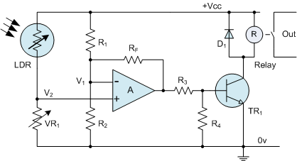
enter image description here

And I'm currently trying to breadboard it, as seen here:
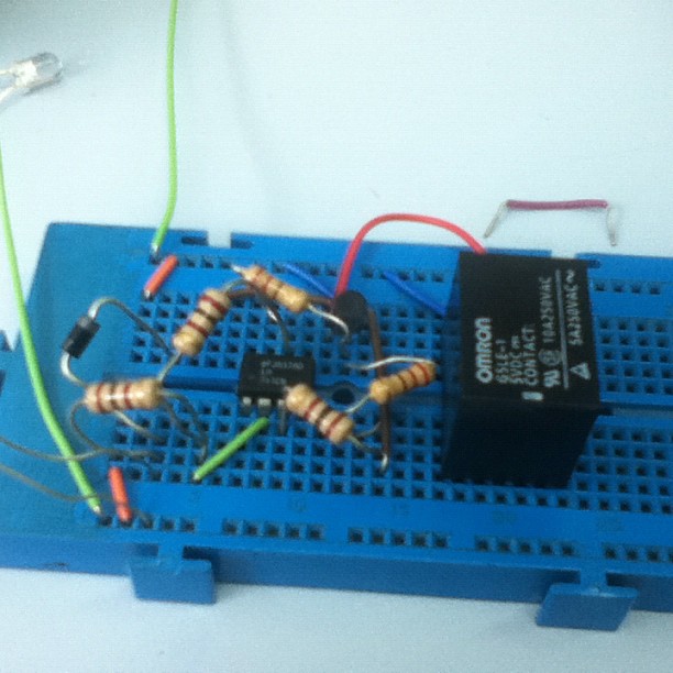
enter image description here

I've been trying to search google on how to wire a Relay, and am not yielding any viable results. I've got a omron 5VDC with 5 pins, 2 on the bottom, 3 on the top.

I think I've figured out that the bottom 2 pins are for power, and the top 3 are for output, in some way. :S I'm going to be connecting the output of the relay to an AND gate to test if a switch is on, and act if both inputs are ON.

Two questions? How do I wire up the relay? and Is the circuit so far matching the diagram? (if you can't tell from the instagram image, forget this question!)

ALSO: I did change it slightly, there is no variable resistor, instead there's an 'average' 100Ohm resistor.

Thank you very much! Cheers, John

\$\endgroup\$
1
  • \$\begingroup\$ Aside: as pictured, it looks like you haven't applied power to your op-amp. The power connections are often left out of the schematic; they are implied. \$\endgroup\$
    – mng
    Commented Dec 4, 2011 at 5:10

4 Answers 4

3
\$\begingroup\$

From the picture it looks like the relay you're using is an Omron G5LE-1. The wiring diagram is available here.

It's a SPDT relay, which means that there is one switch element that moves back and forth between two contacts, unlike the SPST relay used in your circuit diagram. You can still use your relay, but you'll have to wire it so that the "throw" part of the switch is connected to the unused "pole" when the relay is de-energized, and to the other pole when it's energized. From the manufacturers diagram, figure H, it looks like you would want to connect pins 3 and 1 to your output load, leaving pin 4 disconnected. One of pins 2 or 5 would be connected to the collector of the transistor, and the other to the power supply.

\$\endgroup\$
3
\$\begingroup\$

As Bitrex already wrote, the first thing is to look for the datasheet (use a google search or alldatasheet).

Another method would have been in (your case) to connect 5V via alligator clips to the pins you suspect to be the pins for the coil and then listen for the relay to switch. After that, you can draw the circuit diagramm of the remaining pins with a multimeter (continuity test / ohms range).

\$\endgroup\$
3
\$\begingroup\$
  1. 100Ω for VR1 is surprisingly low. You don't show the other values, but it is possible that the positive input to the opamp will never be high enough to turn on the relay like that. I'm guessing your LDR is a CdS cell. Most of those have significantly higher resistance than 100Ω, even in bright light.
  2. Rf should be from the output back to the positive input, not the negative input. As you have it now, the opamp will amplify the signal from the LDR/VR1 divider by a fixed amount. That is not what you want. You want the opamp to detect a threshold and then solidly turn the relay on or off.
     
    You could leave Rf off completely, and the opamp would act as a comparator. That would basically work, but every signal has noise on it, and when the light is right at the threshold the relay may be driven back and forth and "chatter". This is not good. A little positive feedback adds hysterisis. That means once the relay is driven on, a little lower threshold is required to turn it off. Conversely, when the relay is off, a little higher threshold is required to turn it on. You don't need much positive feedback, just enough to be more than the noise and keep the relay from chattering near the on/off light threshold.
\$\endgroup\$
0
2
\$\begingroup\$

You have to remember that basically a relay is a switch.

Instead of using your finger to operate the switch, it uses a magnetic coil running off (in your case) 5VDC.

Two of the contacts, as you have discovered, are the "power". These operate the coil and energise it.

The other three contacts are the "switch" and these operate in exactly the same way as any two-way (SPDT - Single Pole, Double Throw) switch. One pin will be connected to one of the other pins when the power to the coil is off, and to the third pin instead when the power to the coil is on.

You can test which two pins are "normally closed" (i.e., connected when the power to the coil is off) simply enough with a multimeter set to continuity test mode (the beepy mode).

You then know which is the "normally open" connection. With the power to the coil turned on, you can then test the continuity between this pin and the two other pins. The pin which is showing as connected is therefore the "common" pin.

Your "output" from the relay (not that a relay has an output - it's just a switch) is then between this "common" and the "normally open".

As for wiring to an AND gate just to test if a switch is closed or not, that is fairly pointless and extravagant.

Just place the switch in series with the relay's coil so that if the switch is off the relay never gets any power and can't ever switch on. That's what's known as "Wired AND".

\$\endgroup\$

Your Answer

By clicking “Post Your Answer”, you agree to our terms of service and acknowledge you have read our privacy policy.

Not the answer you're looking for? Browse other questions tagged or ask your own question.