1
\$\begingroup\$

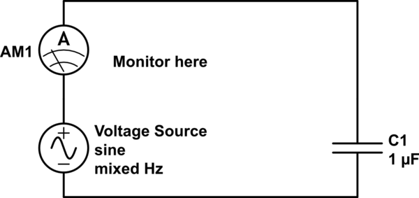
Note: I am an applied mathematician, not an electrical engineer, so apologies if this comes across as silly. I am analyzing the following circuit as part of some modeling related to energy storage systems:

schematic

simulate this circuit – Schematic created using CircuitLab

Where the voltage source is gaussian white noise (hence my use of "mixed Hz" in the schematic software this site uses). This means that the fourier transform of the voltage waveform is flat across all frequencies.

I was wondering if, given the rms Voltage, I could calculate an "equivalent capacitative reactance" \$X_{c,eq}\$ such that:

$$I_{rms} = \frac{V_{rms}}{X_{c,eq}}$$

I've heard of Johnson-Nyquist noise and kTC noise for capacitors, but I don't see how temperature applies here (since they are modelling a physical phenomena).

\$\endgroup\$
5
  • \$\begingroup\$ And your actual question is? \$\endgroup\$
    – PlasmaHH
    Commented Jun 30, 2016 at 12:56
  • \$\begingroup\$ @PlasmaHH oops..yes, added my question. \$\endgroup\$
    – user115412
    Commented Jun 30, 2016 at 12:58
  • 1
    \$\begingroup\$ Actually kTC is not the noise generated by a capacitor as ideal capacitors are noiseless. From the voltage and the current you can indeed detemine Xc and from that the capacitance. \$\endgroup\$ Commented Jun 30, 2016 at 13:38
  • \$\begingroup\$ @FakeMoustache thanks for clarifying. How would one calculate \$X_c\$ for my specific example of gaussian noise? \$\endgroup\$
    – user115412
    Commented Jun 30, 2016 at 13:39
  • \$\begingroup\$ Xc is like a resistor so apply Ohm's law: R = V/I where instead of R you use Xc. As long as you define the magnitudes of Current and voltage in the same way (like both RMS or both peak value) then this should work. EEs normally only apply this using sinusoidal signals but it should apply to noise as well (and as noise can considered the sum of many sinewaves...) \$\endgroup\$ Commented Jun 30, 2016 at 13:45

2 Answers 2

1
\$\begingroup\$

It doesn't really make sense to talk about a single or "effective" value of \$X_C\$ in this context, since as you say, you don't have a single frequency that you're dealing with.

Instead, you need to take a step back and apply a more fundamental relationship:

$$I_C(t) = C\frac{d V_C(t)}{dt}$$

Since you're the mathematician here, I'm not going to tell you how to differentiate a random signal, other than to make a few qualitative comments.

A differentiator functions as a high-pass filter that deemphasizes low frequencies and emphasizes high frequencies. Therefore, if your voltage source is "white" (equal amplitudes at all frequencies), the current value will be very "blue", with arbitrarily high values at arbitrarily high frequencies.

The RMS value of this current (relative to the RMS value of the voltage) will depend on exactly what bandwidth you're considering.

\$\endgroup\$
0
\$\begingroup\$

You may have better luck simulating your voltage source as an equivalent resistor with that amount of thermal noise, as a resistor with no parasitic inductance or capacitance has a flat noise amplitude if you keep the bandwidth the same for each measurement.

Equally you really need to specify the specific bandwidth of your current measuring device, as infinite bandwidth = infinite white noise power = infinite white noise current, how I have approached this in the past has been to break it up into many little steps to brute force it.

So you have a noisy 10000 ohm thermal resistor, lets say you look at it in slices 1Hz apart e.g. 1-2Hz, that is a bandwidth of 1Hz (same value for 100-100 or 25000-25001, if it is different than 1, then it becomes the square root of the bandwidth), at a temperature of 20C it has a thermal noise of 12.72nV RMS,

your resistor has some resistance so it can equally be modeled as a noise current, in this case 1.272pA RMS (12.72E-9 / 1E4), this is with all of the current flowing through that resistor, so anything in parrellel will divert some of this, but never all of it

As your capacitor has some reactance for the frequency you are looking at for that given step (technically impedance, as all capacitors have some equivalent series resistance) you can treat it like finding the current in 1 leg of 2 parallel resistors,

E.g. the step of 1000-1001Hz, the capacitor has an impedance of roughly 159 Ohm, so the current through the capacitor would be Noise Current * (Rz / (Cz + Rz)) note that this value changes with each frequency step, so you would be left to root square sum all of these currents over the bandwidth your interested in,
\$\endgroup\$

Your Answer

By clicking “Post Your Answer”, you agree to our terms of service and acknowledge you have read our privacy policy.