I have 8 analog input coming from various 5v and 3.3v sensors that have to be interfaced to a 3.3v micro-controller. The main system voltage is 24v-48v , i need to protect the ADC inputs against over-voltage from misuse , not ESD events. So if by mistake the 48v is connected instead of the sensor.
after looking into the following threads :
How would I design a protection clipper circuit for ADC input?
ADC over-voltage input protection while keeping accuracy
i tried the following :
- Approach 1: Resistor and Zener
This approach is fine on digital pins but confirmed what people said in the posts about voltage drop and ADC error. I heard that using a shunt regulator like the TL431 instead could help but haven't tried it!?
- Approach 2: Series Resistor and External clipping diodes
The approach works fine it have tries BAS70,BAT54 and similar , in order to get lower drop i have found that using power (1A) schottky is better because they have much lower voltage drop at 1-25mA .
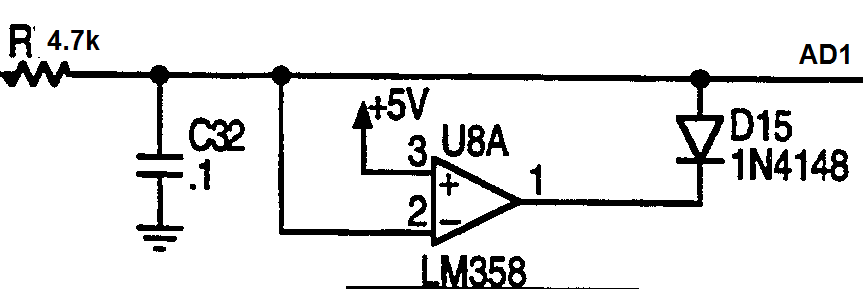
- Approach 3: OPAMP, Resistor and diode
this approach i have found is not very common , and work fairly well , similar to approach 2 but more complicated.
- Approach 4: Unity Gain opamp with internal Clamp
Texas instruments have a product for this role exclusively. OP698
BUT: this lowest single supply is 5v not 3.3v , and the maximum clamping voltage is lower than the rail . and it does not tell how much is the maximum input voltage. and it takes PCB space , 4 resistors and 1 SO-08 IC per input.
Question :
At this point of search i got a bit frustrated and i think now that Approach 2 is the best in terms of robustness and space, please help and state any other approach i am missing ??
I am also interested in exotic solutions similar to automotive Input/ Output ICs that have multiple inputs and protection built in to interface the processors to harsh environment. similar to this MAX6816 used for digital signals.

