4
\$\begingroup\$

Hello I am picking up a project from someone else who has a built a dipole that is connected to a 1:1 transformer with the intention of using it as a current balun. I have noticed that from documents that the balun is supposed to be built with the corresponding polarity
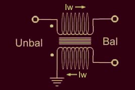
Intended Balun
(source: vk5ajl.com)

From looking at the PCB built I have determined that this isn't how it is wired. It is wired like.
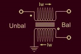
Built Balun

The thing I am wondering is that if this polarity difference is effected my Balun abilities. I haven't really been able to find a explanation about this.

This is the balun I am using: Pulse CX2147

\$\endgroup\$
5
  • 1
    \$\begingroup\$ The induced 180 degree phase shift shouldn't cause any problems, but it may depend on the external circuit. \$\endgroup\$ Commented Jul 12, 2016 at 23:26
  • \$\begingroup\$ From reading I found that when it is hooked up with the correct polarity: "The two windings must be in the same sense (dots at the same end). The magnetic fields of opposing balanced working currents will cancel each other out and so present very little impedance (other than the resistance of the wires) to these currents. Would this still hold up if one of the coils is backwards. Source: vk5ajl.com/projects/baluns.php \$\endgroup\$
    – dwebber
    Commented Jul 12, 2016 at 23:36
  • \$\begingroup\$ @Captainj2001 Forgot to tag \$\endgroup\$
    – dwebber
    Commented Jul 12, 2016 at 23:42
  • 1
    \$\begingroup\$ The only purpose of the balun here is to convert the balanced signal from the dipole antenna to an unbalanced signal that can be used for PCB routing on microstrip or CPW transmission lines. The polarity of the windings here will simply invert the "normal" signal. Equivalently, you could move the antenna \$\lambda/2\$ and achieve the same inversion. \$\endgroup\$ Commented Jul 13, 2016 at 0:30
  • \$\begingroup\$ Sparky's answer is absolutely correct, I was reading the diagram and incorrectly associating the top 2 nodes (Left/Right) as the balanced input and the bottom node as the unbalanced output port. My previous comments are incorrect based on this error (but they would still be true if the balun was wired the way I originally assumed). \$\endgroup\$ Commented Jul 13, 2016 at 2:13

1 Answer 1

1
\$\begingroup\$

Two things you should know. Mouser and other suppliers have listed it as a discontinued part. That means you can buy it cheap while stock last. The second thing is that your second drawing is correct, the way you say it is wired on the PCB. Think about it. For a balanced output you need both a (+) phase (no dot) and a (-) phase (with a dot).

The first drawing will NOT work because there is no difference in the output wires-no signal. Also the Iw marking is wrong in the top drawing as both currents are flowing in the same direction. Your instincts were correct. The PCB is wired as per drawing 2.

\$\endgroup\$

Your Answer

By clicking “Post Your Answer”, you agree to our terms of service and acknowledge you have read our privacy policy.

Not the answer you're looking for? Browse other questions tagged or ask your own question.