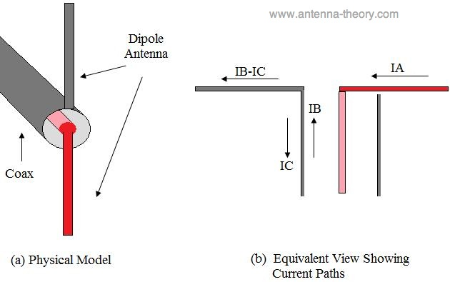
Let's consider a coaxial cable which supplies a dipole antenna. My reference for all my statements is here.
- My reference says:
Note that the current along a transmission line should be of equal magnitude on the inner and outer conductors, as is typically the case. Observe what happens when the coax is connected to the dipole. The current on the center conductor (the red/pink center core of the coax, labeled IA) has no where else to go, so must flow along the dipole arm that is connected to it. However, the current that travels along the inner side of the outer conductor (IB) has two options: it can travel down the dipole antenna, or down the reverse (outer) side of the outer conductor of the coaxial cable (labeled IC in Figure 1).
Well, I don't understand why the current in the outer conductor should be divided in IB ("direct") and IC ("Reverse"). I see it in this way: the coaxial cable is supplied by a voltage or current source, with its terminals connected one to the shield and one to the inner conductor. The current in the inner conductor is equal to the total current in the shield. The last one, because of skin effect, flows mainly on the shield surface, so it goes partially in the inner side and partially in the outer side of the shield. Both current have the same direction, as the current that flows any conductor surface at RF.
I'd say that IA is equal to the total current flowing in the shield surface. And a dipole with arms connected to the whole shield conductor and to the inner conductor will receive equal currents. Which is the mistake in my analysis?
As I see, the unbalanced nature of the coaxial cable is due to its shield having both an inner and an outer surface. So, it's a parasitic effect of the coaxial cable, and I'd say that it's absent for instance in simple 2-wires transmission line. Is it correct?
Again, the problem is the parasitic current IC in a coaxial cable. Well, what does it has to do with this usual representation of a balun as a converter from a grounded signal to a floating signal?
Even in a 2-wires transmission line, which I'd say it's balanced, we consider one conductor as GND, like in the following picture (indicated as "0").


