0
\$\begingroup\$

Pardon the possible simplicity of this question but I am incredibly new to antenna design. So, I settled on a simple loop antenna, made of 14awg copper and about 18inches circumference (tuned to 644Mhz) hooked to a Balun. I picked that size because that is the weakest channel I wish to receive. The antenna picks up a pile of other channels just fine but still gets no viable signal on that channel. I know that I cant just go about making things larger arbitrarily so how do I increase gain? Can I somehow add other loops (I think I saw a picture of this) and if so how do I chain these together?

N.B. I am height limited and this is stuck inside so the old advice of put it higher and remove obstructions is difficult.

\$\endgroup\$
5
  • \$\begingroup\$ Can you report the calculations that have you made for the circumference? \$\endgroup\$
    – clabacchio
    Commented Jan 20, 2012 at 16:16
  • \$\begingroup\$ I used an online calculator @ csgnetwork.com/freqwavelengthcalc.html. I used 644Mhz as the input and clicked full wave \$\endgroup\$ Commented Jan 20, 2012 at 21:02
  • 1
    \$\begingroup\$ You'd probably do better with a directional antenna, e.g. a small Yagi. \$\endgroup\$
    – Paul R
    Commented Jan 20, 2012 at 21:36
  • \$\begingroup\$ @PaulR, I always thought loops/bow-ties were the choice for uhf due to the higher frequencies acting on magnetic resonance (Warning: I may not have any idea what I am talking about) \$\endgroup\$ Commented Jan 20, 2012 at 21:56
  • 1
    \$\begingroup\$ @bobnix, the standard is called a whip antenna actually. It is the electric field couterpart of a loop. A loop is a magnetic field dipole, a dipole is an electric field dipole. \$\endgroup\$
    – Kortuk
    Commented Jan 20, 2012 at 23:51

2 Answers 2

0
\$\begingroup\$

I'll just write down some theory, based on what I've studied.

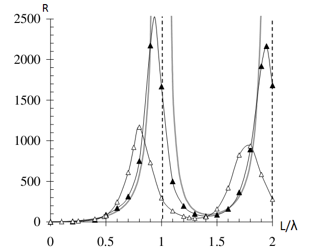
Your problem may be cause by the fact that you realized a full wave antenna: this size gives you a very high input resistance, that makes difficult to transfer power to the receiver.

Try an half-wave antenna, that is the recommended size. That's also the reason because the other channels work better, because the peak of the resistance is centered where the length of the antenna is equal to the wavelength.

Resistance over L/lambda for simple dipole antenna

This image shows the radiation resistance shown by the simple dipole antenna related to the antenna length/wavelength ratio. I'm sorry that i couldn't find the same figure for the loop antenna, but I hope it gives the idea.

About the bow-tie antenna, it's like the folded dipole (and so also similar to the loop antenna) but it has a wider resonant band, so it's less sensible to frequency change.

\$\endgroup\$
3
  • \$\begingroup\$ Oh, I thought the idea of half or quarter waves were just to reduce size and otherwise bigger is better. Like I said in the OP, I am a radio neophyte. \$\endgroup\$ Commented Jan 20, 2012 at 22:21
  • \$\begingroup\$ That chart is very helpful. Not only for its contents but I remember seeing a chart like that for loops and being generally lost as to what I was seeing. \$\endgroup\$ Commented Jan 20, 2012 at 23:10
  • \$\begingroup\$ I'm not sure where you found those curves but they are wrong - loops resonate at half wavelength too! \$\endgroup\$
    – neonzeon
    Commented Nov 20, 2016 at 2:20
1
\$\begingroup\$

Look at Nikolova's lecture on loops (page 10) showing reactance and resistance of a loop.

Curve b does not really show it, but the reactance is zero (i.e. quickly swings from high + to high -) around (but not exactly at) 0.5 λ (half wavelength).

This is the first point where you only see resistance, i.e. the reactance is zero. This is also the point that you need for a well matched antenna - maximum power is transferred to the receiver. (if antenna and receiver resistances are equal)

Curve A shows that the resistance goes way above 1k at 0.5 λ.

So, assuming you want to match to, say, 50 ohms, here is one way to do it:

  1. Find the 50 ohm resistance point on curve a. You'll see it's around 0.37 λ.

  2. Now look at curve b to see how much reactance you have at 0.37 λ. You'll see that it's high - around 300 ohm or more, inductive. So, insert a capactor with around 300 ohms of capacitive reactance (at 644 MHz) in series with the loop to cancel out the 300 ohms of inductive reactance.

You are not going to get this right at your first try. Therefore, you have to find a way to measure the loop's impedance so you can iterate to the right loop size (to get the resistance right) and to the right capacitor size (to cancel out the inductive reactance).

The loop is great for direction finding, because it has a very sharp null. However, this is not a good wideband antenna. If you want to monitor a wide band of frequencies, I recommend using a discone antenna.

I also recommend reading the rest of Nikolova's lecture on loops - it's a treasure trove of good and accurate information.

Finally, technically you are not really increasing the gain of the loop antenna (because the gain (specifically, directionality) of a specific size/frequency of loop antenna is fixed) This recommendation is in essence a method to properly match a half-wave loop to your receiver/transmission line, which I strongly suspect is the culprit in your case.

\$\endgroup\$
2
  • \$\begingroup\$ The one-wavelength loop has resonant impedance near 100 ohms. The OP's circumference calculation is about right. But #14 AWG wire diameter is significant compared to 18" wire length, so resonance may be approximate. He may benefit from impedance matching to receiver input too. He may also have run afoul of polarization mismatch. The loop is directional too. \$\endgroup\$
    – glen_geek
    Commented Nov 20, 2016 at 2:34
  • \$\begingroup\$ Yes, that's easy to confirm on Nikolova's curve a. However, my two key points are: 1) you only need a half wave loop 2) you need to know about finding the desired point of resistance (curve a) and reactance (curve b) and then cancel out the reactance. \$\endgroup\$
    – neonzeon
    Commented Nov 20, 2016 at 2:47

Your Answer

By clicking “Post Your Answer”, you agree to our terms of service and acknowledge you have read our privacy policy.

Not the answer you're looking for? Browse other questions tagged or ask your own question.