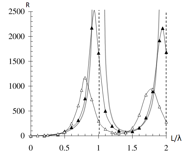
Look at Nikolova's lecture on loops (page 10) showing reactance and resistance of a loop.
Curve b does not really show it, but the reactance is zero (i.e. quickly swings from high + to high -) around (but not exactly at) 0.5 λ (half wavelength).
This is the first point where you only see resistance, i.e. the reactance is zero. This is also the point that you need for a well matched antenna - maximum power is transferred to the receiver. (if antenna and receiver resistances are equal)
Curve A shows that the resistance goes way above 1k at 0.5 λ.
So, assuming you want to match to, say, 50 ohms, here is one way to do it:
Find the 50 ohm resistance point on curve a. You'll see it's around 0.37 λ.
Now look at curve b to see how much reactance you have at 0.37 λ. You'll see that it's high - around 300 ohm or more, inductive. So, insert a capactor with around 300 ohms of capacitive reactance (at 644 MHz) in series with the loop to cancel out the 300 ohms of inductive reactance.
You are not going to get this right at your first try. Therefore, you have to find a way to measure the loop's impedance so you can iterate to the right loop size (to get the resistance right) and to the right capacitor size (to cancel out the inductive reactance).
The loop is great for direction finding, because it has a very sharp null. However, this is not a good wideband antenna. If you want to monitor a wide band of frequencies, I recommend using a discone antenna.
I also recommend reading the rest of Nikolova's lecture on loops - it's a treasure trove of good and accurate information.
Finally, technically you are not really increasing the gain of the loop antenna (because the gain (specifically, directionality) of a specific size/frequency of loop antenna is fixed) This recommendation is in essence a method to properly match a half-wave loop to your receiver/transmission line, which I strongly suspect is the culprit in your case.

