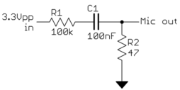
This seems to be a common smartphone project, but I haven't seen circuit diagrams with explanations.
What filter network (or resistor network, or other buffering circuitry) should be used to connect a 3.3V digital output (say from an Arduino or similar) producing a square wave at a suitable audio frequency (say around 300 to 3000 Hz) to the microphone input on the headset jack of a typical mobile phone (say an iPhone 4), so as to:
not damage the mic input circuitry of the phone,
provide a reasonably high signal-to-noise ratio, and
not significantly distort the spectral portion of the digital square wave that is within the mic input audio frequency bandwidth? (to allow experimentation with digital modulation schemes beyond simple FM.)
ADDED: The following text has been moved to a new question:
In the opposite direction: how should a mobile phone headphone audio output be interfaced to a microcontroller digital input? (assume no audio frequency capable A/D is available.)

