7
\$\begingroup\$

I want a 500uF capacitor. Theoretically, I should be able to place 5 100uF capacitors in parallel to achieve 500uF of capacitance.

However, are there any side effects of practically implementing this? Are there non-ideal effects that I should account for?

Note: I'm looking for a 500uF surface mount ceramic capacitor. I've been able to find these, however, the tolerances are only +/- 20%. Furthermore, I've only found one manufacturer of these and I would prefer not be too dependent on a single manufacturer.

\$\endgroup\$
11
  • \$\begingroup\$ Resistance of the wires, some current loops. \$\endgroup\$
    – Eugene Sh.
    Commented Oct 28, 2016 at 15:30
  • 6
    \$\begingroup\$ What are you doing with a 500 uF cap that 20% tolerance is a problem? \$\endgroup\$
    – The Photon
    Commented Oct 28, 2016 at 15:34
  • 7
    \$\begingroup\$ Then make it 600 uF so that 20% less is acceptable. The problem is not with the 500 uF cap, but with your spec. \$\endgroup\$ Commented Oct 28, 2016 at 15:37
  • 1
    \$\begingroup\$ @JRE: No, the inductance goes down too. Multiple inductors in parallel is less inductance. \$\endgroup\$ Commented Oct 28, 2016 at 15:38
  • 4
    \$\begingroup\$ @Teague, use two 470-uF caps, or 3 220-uF caps, or one 680-uF. Or 10 100-uF caps. This isnn't sound like an application where you can have too much capacitance, only too little. \$\endgroup\$
    – The Photon
    Commented Oct 28, 2016 at 15:51

5 Answers 5

7
\$\begingroup\$

Paralleling capacitors is fine electrically. That actually reduces the overall ESR and increases the ripple current capability, usually more so than a single capacitor of the desired value gets you. There is really no electrical downside to this.

The prominent non-ideal effects are cost and space.

\$\endgroup\$
1
  • 2
    \$\begingroup\$ I suggest you read my link to update your library wealth of wisdom \$\endgroup\$
    – D.A.S.
    Commented Oct 28, 2016 at 15:52
3
\$\begingroup\$

Depending on the industry you are dealing with, dormant failure modes could be a consideration.

5off 100uF @ +-20% means you maximum spread of terminal capacitance is: 400uF --> 600uF. Sure what are the odds that all are at the maximum or at their minimum...

If one capacitor failed open-circuit (solder, mechanical etc...) the total span is 320uF --> 480uF. & the nominal range lies within this, dormant failure that is not quickly detectable during any production PAT's.

\$\endgroup\$
2
\$\begingroup\$

Parallel capacitors can actually introduce resonance at high frequencies, especially if they have different values. See this link for more information. Especially the plot on page 3.

This is actually a big problem when decoupling BGAs as you cannot get the capacitors as close as you would like, and you need to use different values.

\$\endgroup\$
3
  • 1
    \$\begingroup\$ This might be useful information for a future reader, but probably doesn't apply to OP, since he's talking about a value that's most likely an electrolytic type (with higher ESR to reduce this effect) and not talking about combining different values. \$\endgroup\$
    – The Photon
    Commented Oct 28, 2016 at 16:12
  • 1
    \$\begingroup\$ Yeah, I know. I just wanted to put it here for reference. \$\endgroup\$
    – user110971
    Commented Oct 28, 2016 at 16:31
  • \$\begingroup\$ Also, it depends how far the caps are. You have inductance on the traces. \$\endgroup\$
    – user110971
    Commented Oct 28, 2016 at 16:32
1
\$\begingroup\$

Yes there is a huge penalty for ignoring ESR in parallel caps at RF frequencies.

Due to Resonant (//) and anti-resonant (series) behaviors in parallel caps, ultra-low ESR ceramic caps can actually amplify noise due to high series Q, even if parallel (//) Q is low.

Murata has championed this by raising the ESR a bit in their RF ceramic caps to reduce the Series Q and flatten the overall "low Z bandwidth" in SMPS filters, which becomes critical >1MHz switching rates.

You must be aware of ESR*C time constant in all shunt caps, SRF and Series Q as well for optimal ripple rejection of harmonics.

Proof:

How much resistance does the capacitor itself contribute to an RC circuit?

For more experience on ESR vs value of C, ref my info (which I can backup) What happened to electrolytic capacitors in the 21st century?

\$\endgroup\$
1
  • 5
    \$\begingroup\$ 500 uF is not likely to be an "ultra-low ESR ceramic". And nobody's mentioned combining different values, which is usually how anti-resonant behavior is found. \$\endgroup\$
    – The Photon
    Commented Oct 28, 2016 at 16:07
1
\$\begingroup\$

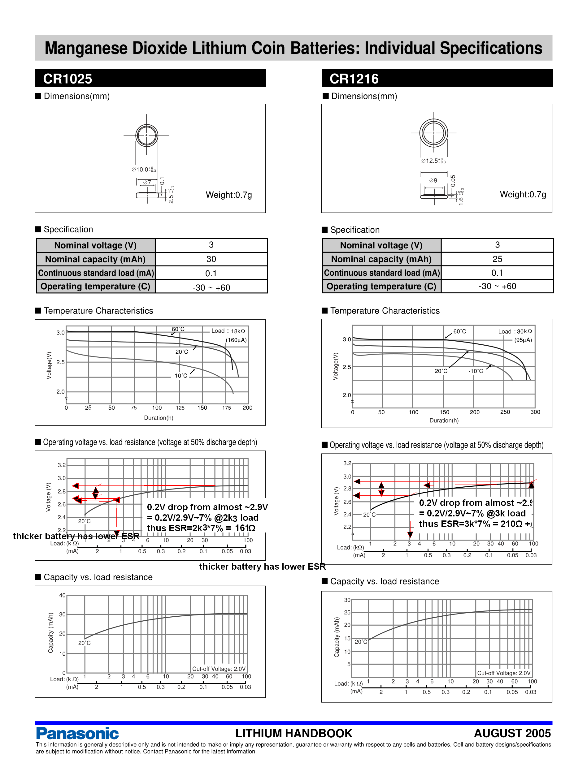
Your problem is not the ESR of the caps , rather it is the high ESR of the coin cell ( based on your previous questions)

Solution: Use a better battery such as CR123A with much lower ESR 3.00V <<1Ω ESR

Lithium primary cells have FAR more capacitance than electrolytic capacitors at same cost or size.

  • Load regulation error % drop in coin cell voltage = RL/(RL+ESR(bat)

Proof of ESR ( ignoring estimate tolerances from graph but for 50% SoC cell.)

Sample datasheet

enter image description here

  • Rule of Thumb
    • CR1025 has 30 mAh capacity at 0.1mA load and ESR of ~161 Ω
    • CR1216 has 25 mAh capacity at 0.1mA load and ESR of ~210 Ω

- thus Ah capacity is inverse to ESR of battery or mAh*ESR = constant - for given family for chemistry and supplier

  • exactly the SAME is true for any capacitor where ESR*C = constant
    • for any given family and similar size
    • but varies between internal chemistry, quality, supplier.
    • as cap or battery wears out ESR rises sharply and C drops sharply as mAh drops .
  • ESR*C < 1us for ultra-low ESR
  • ESR*C - 100us to >1 ms for general purpose alum electrolytic
  • ESR*C <0.01us for low ESR ceramic in small values.
\$\endgroup\$

Your Answer

By clicking “Post Your Answer”, you agree to our terms of service and acknowledge you have read our privacy policy.

Not the answer you're looking for? Browse other questions tagged or ask your own question.