2
\$\begingroup\$

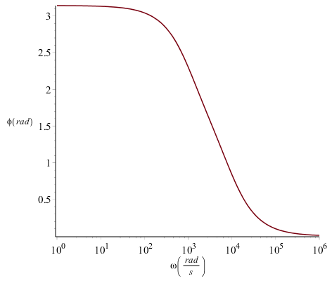
I don't really understand what the phase shift in a bode plot means. Is it the shift of the output compared to the input signal? And how can I intuitively interpret the meaning of the second diagram in this bode plot? I don't really understand why the shift goes to zero as the angular velocity (omega) goes to infinity (and why the amplification goes to zero as omega goes to infinity). What's there relationship?

This is the bode diagram I'm talking about: enter image description here
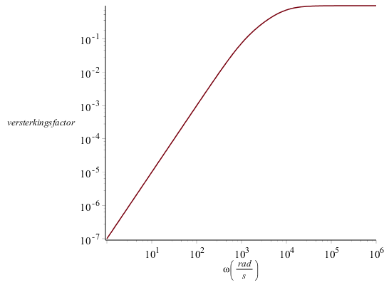
enter image description here

This bode plot corresponds to this circuit: enter image description here
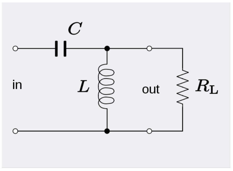
I used these values for the plot: Rl = 100, C = 10^(-6) and L = 0.1

\$\endgroup\$
5
  • \$\begingroup\$ The capacitor is an open circuit at DC and a short circuit at infinite frequency. The inductor has the opposite characteristic. Hence, e.g., a high frequency sine wave passes directly through the capacitor without modification, and finds itself across the resistor (the inductor is open-circuit, hence can be considered disconnected). Similar analysis at DC, with roles reversed. The amplification does not go to zero at infinite frequency, but to \$10^{0}=1\$ \$\endgroup\$
    – Chu
    Commented Nov 4, 2016 at 14:37
  • \$\begingroup\$ Try it without the inductor and see if you understand it then. \$\endgroup\$ Commented Nov 4, 2016 at 14:47
  • \$\begingroup\$ I understand indeed! I had some problems with the combination of the capacitor and the inductor, but by using the information that a capacitor doesn't modify the signal for high frequencies I understand now. Thanks :) \$\endgroup\$ Commented Nov 4, 2016 at 14:52
  • \$\begingroup\$ for giggles \$\pi\$ vector plots and resonant switch option in slow motion ~1% goo.gl/Hk1HWo in java sim \$\endgroup\$
    – D.A.S.
    Commented Nov 4, 2016 at 16:58
  • \$\begingroup\$ a much more interesting result occurs with peaking using high Q=R/Zc(f) ratio at resonant freq or break point of filter where amplification gain (versterkings factor) =Q for eg 10 Kohm \$\endgroup\$
    – D.A.S.
    Commented Nov 4, 2016 at 17:53

1 Answer 1

4
\$\begingroup\$

Is it the shift of the output compared to the input signal?

It depends what you're making a Bode plot of.

If you're plotting a transfer function \$V_{out}/V_{in}\$, then yes, it will be the shift of the output compared to the input.

If you're plotting an impedance \$V_{in}/I_{in}\$ then it's the phase shift of the voltage compared to the current.

I don't really understand why the shift goes to zero as the angular velocity (omega) goes to infinity

Because in the limit, the capacitor becomes a short circuit and the inductor becomes an open. So the equivalent circuit is just connecting the input directly across the load resistance.

and why the amplification goes to zero as omega goes to infinity

Same reason. The equivalent circuit in the high frequency limit is just applying the input directly across the output. 0 dB gain is equivalent to linear gain of 1.

\$\endgroup\$
3
  • \$\begingroup\$ there is \$\pi\$ phase shift with 2 reactive parts due to \$\pi/2\$ per part \$\endgroup\$
    – D.A.S.
    Commented Nov 4, 2016 at 16:56
  • \$\begingroup\$ @TonyStewart.EEsince'75, there's \$\pi\$ phase shift between the low frequency response and the high frequency response, but the phase shift at high frequencies goes to 0. \$\endgroup\$
    – The Photon
    Commented Nov 4, 2016 at 17:40
  • \$\begingroup\$ exactly , just thought it could be included in your asnswer \$\endgroup\$
    – D.A.S.
    Commented Nov 4, 2016 at 17:47

Your Answer

By clicking “Post Your Answer”, you agree to our terms of service and acknowledge you have read our privacy policy.

Not the answer you're looking for? Browse other questions tagged or ask your own question.