0
\$\begingroup\$

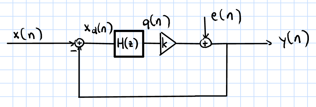
I am currently reading the book Continuous-Time Sigma-Delta A/D Conversion to get myself a better understanding of \$ \Sigma \Delta\$ converters. Unfortunately I got stuck at the point where noise-shaping is explained. The chapter started clearly, saying that for studying the effects of noise, the quantizer can be approximated by a linear model, which then leaves us with a linearized \$ \Sigma \Delta\$ modulator as shown at the bottom.

With this model we want to achieve two different transfer functions, one for \$x(n)\$ and another for \$e(n)\$.

$$ Y(z)=STF(z)X(z)+NTF(z)E(z) $$

STF ... Signal Transfer Function, NTF ... Noise Transfer Function

Since the noise shall occur at high frequencies and the signal at low frequencies, it seems clear that the STF should be a low-pass and the NTF a high-pass filter.

Now the author states that this leads to the following concrete transfer functions:

$$ STF(z)=\frac{1}{\frac{1}{H(z)k} + 1} \\ NTF(z)=\frac{1}{H(z)k + 1} $$

No further explanation. How is it possible to conclude that the STF and NTF need to look like that? Furthermore, how can we conclude that the simplest \$H(z)\$ is an integrator?

enter image description here

\$\endgroup\$
2
  • \$\begingroup\$ It seems that you have problems with the specific document you read - have you looked for alternative explanations on the internet. I've seen many. \$\endgroup\$
    – Andy aka
    Commented Dec 29, 2016 at 15:12
  • \$\begingroup\$ @Andyaka Yes, but the ones I read so far did not go into great detail. Most of them simply stated that an integrator is used, but did not explain why and how you would derive this mathematically. Do you have any recommendations of literature? \$\endgroup\$
    – Daiz
    Commented Dec 29, 2016 at 15:46

1 Answer 1

3
\$\begingroup\$

Noise shaping refers to the spectral shaping of the quantization noise. It is assumed that the input signal of the quantizer is sufficiently "busy" so that it can be modeled as a linear gain element with some additive noise.

The ultimate goal is to get an output signal that represents the input signal as closely as possible. The modulator shown in your post is the most common type, a lowpass delta-sigma modulator, it works best for low-frequency input signals.

Looking at $$ Y(z)=STF(z)X(z)+NTF(z)E(z) $$ we see that for an accurate representation of the input signal X(z) the STF should be about 1 and the NTF should be as small as possible.

To fulfill the first requirement STF ~ 1 we can look at $$ STF(z)=\frac{1}{\frac{1}{H(z)k} + 1} $$ and quickly see that we only need to have an \$H(z)\$ that is much larger than 1 for small frequencies. An integrator will be a perfect fit, however other filter types are possible as well.

For the second condition, quantization noise suppression at low frequencies, the expression $$ NTF(z)=\frac{1}{H(z)k + 1} $$ shows, that again \$H(z) \gg 1\$ for low frequencies is required. Again this can be achieved with an integrator.

\$\endgroup\$
3
  • \$\begingroup\$ Thank you for your answer! I understood now why an integrator is chosen, based on the formulas of the STF and NTF. But do you have an idea where those formulas come from? How are they derived? \$\endgroup\$
    – Daiz
    Commented Dec 29, 2016 at 16:10
  • \$\begingroup\$ The equations result directly from the linear model. \$\endgroup\$
    – Mario
    Commented Dec 29, 2016 at 16:18
  • \$\begingroup\$ Yep, true, I see it now .. \$\endgroup\$
    – Daiz
    Commented Dec 29, 2016 at 16:24

Your Answer

By clicking “Post Your Answer”, you agree to our terms of service and acknowledge you have read our privacy policy.

Not the answer you're looking for? Browse other questions tagged or ask your own question.