0
\$\begingroup\$

We have an off-grid UK home on occasion powered by a generator (MOSA GE 6000 SX/GS).

Due to the design of the generator, it has two modes: centre-tapped-earth 110 V, and 230 V. When running in 230 V mode, the two windings in the generator are connected in series; in 110 V mode, the windings are operated in parallel.

The result is that when the house is powered (generator operating in 230 V mode) there is 50 volts between the neutral and earth, and 180 volts between the live and earth.

I am told by an electrician that the neutral should be 0V (tied to earth) while the manufacturers of the generator unsurprisingly say that 50 volts on the neutral is fine.

Which is correct?

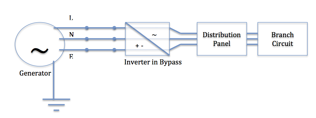
System Diagram generator diagram Note: Generator is connected to earth by an earth stake connected to the case.
Portion of internal circuit diagram of generator: enter image description here
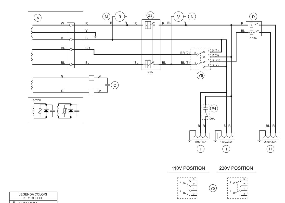
Note 1: BL=Neutral (230V), BR=Live (230V). Note 2: The manufacturer added that the two windings are: connected in series when the generator is in 230 V mode, and connected in parallel when in 110 V mode.

\$\endgroup\$
15
  • 3
    \$\begingroup\$ This depends on how your system is normally grounded. Show a diagram of your setup. \$\endgroup\$ Commented Jan 9, 2017 at 12:28
  • \$\begingroup\$ Generator -> Inverter Bypass -> Underground Cable (300 meters) -> Main Distribution Panel -> Branch Circuits / In-house wiring; Normally when the inverter is operating, the neutral is connected to earth (inverter has a relay controlling this during bypass). Single phase L-N voltage is 230V 50Hz. \$\endgroup\$
    – xirt
    Commented Jan 9, 2017 at 12:34
  • \$\begingroup\$ Show circuit diagram with your earting rod/point. \$\endgroup\$
    – winny
    Commented Jan 9, 2017 at 12:40
  • 1
    \$\begingroup\$ The generator RCD / GFI trips when Neutral is connected to earth 'downstream' of the generator. \$\endgroup\$
    – xirt
    Commented Jan 9, 2017 at 12:54
  • 1
    \$\begingroup\$ "centre-tapped-earth 110 V, and 230 V." Is there any documentation how earth is connected internally in 230 V mode? \$\endgroup\$
    – winny
    Commented Jan 9, 2017 at 13:05

3 Answers 3

3
\$\begingroup\$

The portable generator is designed primerally to provide a 110V center-tapped earth supply as is normally used on UK construction sites. The 230V output is something of an afterthought which is why you end up with it referenced to earth in a weird way.

In the standards for modern appliances in Europe there is no expectation that the "neutral" pin is at earth potential. So powering modern appliances off the generator should be safe.

OTOH in UK house wiring it is normal to assume that neutral is at earth potential. We don't normally put any overcurrent protection in the neutral and we frequently work on circuits with only the live isolated.

As I see it you have a few options, each with it's pros and cons.

  1. Make sure all circuits are RCD protected with a double pole RCD (note that most RCBOs are only single pole isolating) to mitigate the lack of overcurrent protection in the "neutral" and place warning notices so people don't try to work on circuits that are only single pole isolated.
  2. Set up the consumer unit with double-pole breakers. This is a good option electrically but can get kind of costly as double pole breakers are not widely used.
  3. Modify the generator, remove the existing earth reference and add a new one at the neutral end of the winding. Downside here is you will almost certainly be voiding the warranty and the 110V output will no longer be the center-tapped earth supply expected on UK construction sites.
\$\endgroup\$
1
  • \$\begingroup\$ Another thought is to run the inverter in charge & invert mode (rather than bypass). It seems a little more convoluted, but would isolate the 50V neutral problem. \$\endgroup\$
    – xirt
    Commented Jan 9, 2017 at 15:21
0
\$\begingroup\$

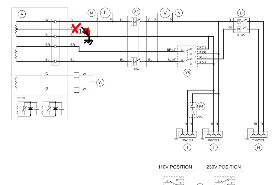
It is safe as long as you don't use any 115V in the 230V series position. But what it tells me is your connection is offset by the generator Y to ground connection , which makes no sense in the 230Vac position as it would force a Neutral offset of 115V/2 out of 230V. ??

In North America we have 3 wire plus ground service with 240Vac and Neutral grounded at outside transformer giving 120 and antiphase 120 for small items and 240V for large items (Stove + dryer). If you have no need for 110V, there no necessity to change.

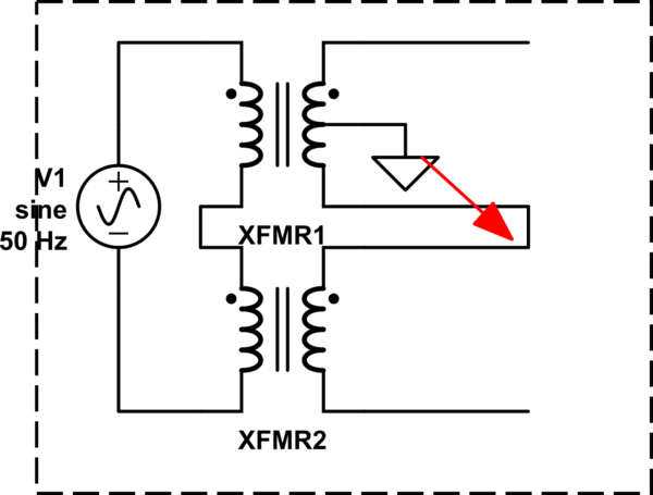
But you wanted to anyways... I would Remove the generator 110V coil centre tap to ground and move gnd to the common connection between the series windings. Then in fact it would be just like North America(3wire+Gnd, 240V single split phase) you could then also use this as the Neutral connection for 120V uses if any. enter image description here

schematic

simulate this circuit – Schematic created using CircuitLab

\$\endgroup\$
0
\$\begingroup\$

There is definitely an expectation in most standards that there is little to no voltage between Neutral and Earth. Fix the wiring so the correct end of the output winding is Earthed in your configuration.

The US National Electrical Code 210.19A.1 states in Informational Note 4: ...limits the voltage drop in a branch circuit to 3% (5% total for feeder and branch circuit) for a reasonable efficiency of operation. Based on this the N-G voltage limit on a single phase 120 VAC circuit is 3.6 VAC and for a single phase 220 VAC circuit 6.6 VAC (equal to the allowable voltage drop on the hot wire).

This informational not in the NEC makes the following assumptions:

  1. Earth/Ground and Neutral are bonded at a single point in your system
  2. The voltage differential between Neutral and Earth is due to current flow in the Neutral wire (voltage drop).
\$\endgroup\$

Your Answer

By clicking “Post Your Answer”, you agree to our terms of service and acknowledge you have read our privacy policy.

Not the answer you're looking for? Browse other questions tagged or ask your own question.