1
\$\begingroup\$

I am from India. In our country we get 3 phase electricity only for 8 hours and remaining 16 hours either we have single phase electricity or no electricity at all.

In three phase mode:

  • The Voltage difference between any two phase is 440V AC
  • The Voltage difference between any Phase and Neutal/Earth is 230V AC

In single phase mode:

  • The Voltage difference between any two phase is 230V AC
  • The Voltage difference between any Phase and Neutral/Earth is 150V - 180V AC

I want to light a bulb.

When there is single phase electricity:

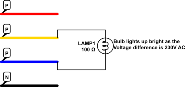
  • If I join the connections of a Bulb to a Phase and a Neutral:

schematic

simulate this circuit – Schematic created using CircuitLab

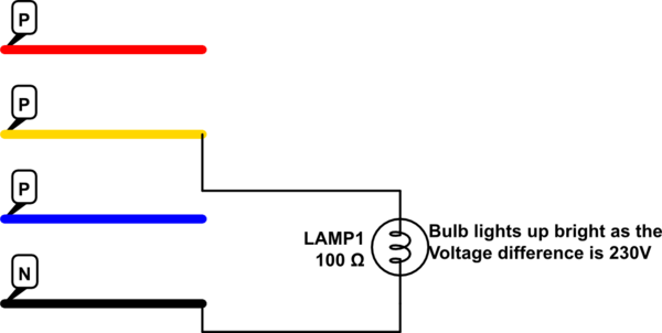
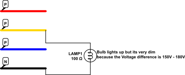
  • If I connect the two connections of bulb to the two Phases as shown in diagram:

schematic

simulate this circuit

When there is three phase electricity:

  • If I join the connections of a Bulb to a Phase and a Neutral:

schematic

simulate this circuit

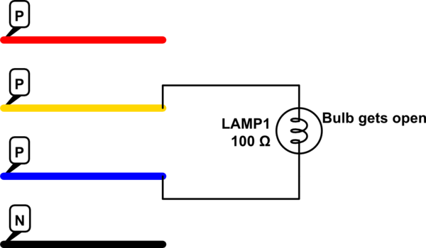
  • If I connect the two connections of bulb to the two Phases as shown in diagram:

schematic

simulate this circuit

So, my problem is:

When there is single phase electricity, I connect my bulb with two phases as shown in diagram2 which lights up my bulb very bright. Now I am doing some work and if Electric board cuts the power supply for 3-4 minutes and then Electric board gives 3 phase electricity, I loose my bulb. So, every time such scenario happens, I had to change the connections of my bulb or I would loose it.

What I tried:

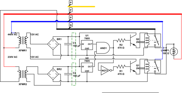
So, I tried to develop a circuit which does this thing automatically for me:

schematic

simulate this circuit

Requirement:

The green boxes in the above diagram are the unknown components. If I apply 440V or very near to that to the primary coil of XFMR1, then only U1 should get the voltage else U1's input should not get any Voltage.

Similarly, If I apply 230V or very near to the Primary Coil of XFMR2, then only U2 should get input else U2's input should not get any Voltage.

Idea after the requirements are satisfied:

So, the idea here is, If Government supplies single Phase electricity:

  • XFMR1 gets 230V difference between two phases and so, it will produce near about 7 Volts in the secondary coil. So, the green box will not output any voltage to the input of U1.

  • Similarly, XFMR2 gets 150-180V difference between a Phase and Neutral, which will produce near about 7-8V in the secondary coil. So, this green box will also not output any voltage. As a result U2 will not get any voltage.

So, both the inputs to AND gate will be 0, which will not turn on RLY1. The input to the NOT Gate will be 0, so it will output 1 and thus RLY2 will start.

If Government supplies 3 Phase electricity:

  • XFMR1 gets 440V difference between two phases and so, it will produce near about 12 Volts in the secondary coil. So, the green box will give output as 12 Volts to the input of U1.

  • Similarly, XFMR2 gets 230V difference between a Phase and Neutral, which will produce near about 12V in the secondary coil. So, this green box will also output 12V. As a result U2 will get 12V input.

So, both the inputs to AND gate will be 1, which will turn on RLY1. The input to the NOT Gate will be 1, so it will output 0 and thus RLY2 will stop.

\$\endgroup\$
8
  • \$\begingroup\$ If you can stand a very small period of higher voltage when in low voltage mode (probably 10's of milliseconds, you can use a very simple solution. Without extra logic circuitry provide a relay that operates when 400VAC is applied but not when 230 VAC is applied (or 230/180 if connected phase to neutral) and switch connection with this relay. If an interruption to service when voltage increases is acceptable you could use a relay which disconnects supply when voltage switches from low to high. The relay could use a 400v:12V (say) transformer as you have shown to allow use of ... \$\endgroup\$
    – Russell McMahon
    Commented Nov 12, 2016 at 11:46
  • \$\begingroup\$ ... a 12 V coil relay. If you use a bridge rectifier (gettiun more complex :-) ) you can use a DC relay. Then you can adjust pull-in/dropout voltage easily. Adding a series resistor in the coil circuit raises dropout voltage but possibly not by enough. Adding a zener diode in series with the DC feed provides a greater difference. eg say input is 440:230V as power switches. Convert this with transformer to 12V:6.3V. Convert to DC giving about 15V:8V say. Adding a series zener of say 8.2V means a relay coil will see about (15-8.2):(8-8.2) ~= 7V:0V so a 6V coild relay will switch well. \$\endgroup\$
    – Russell McMahon
    Commented Nov 12, 2016 at 11:56
  • \$\begingroup\$ NB: Is it really 440V:230V or 400V:230V? \$\endgroup\$
    – Russell McMahon
    Commented Nov 12, 2016 at 11:56
  • \$\begingroup\$ For interest only - where in India? (I've so far visited, Chennai, Pune, New Delhi, Agra, Mumbai). \$\endgroup\$
    – Russell McMahon
    Commented Nov 12, 2016 at 12:02
  • \$\begingroup\$ @RussellMcMahon Well, I really never measured voltage between two phase. But the electricians here say its 440 V. BTW I am from Rajkot, Gujarat. \$\endgroup\$
    – Vishal
    Commented Nov 12, 2016 at 13:49

3 Answers 3

1
\$\begingroup\$

Your idea should work but I feel more inclined to suggest a different approach...

Extract what voltage you can using a 3 phase bridge rectifier and use a powerful buck/boost regulator that can deliver a DC voltage suitable for lighting ONLY the lights. This might mean a re-wire for just the lighting circuits because there is no way this would work with a lot of old fashioned equipment that use step down transformers.

With your idea I would be worried that in the time it takes to decide if the voltage needs stepping down to a lower level, the light bulbs would be severely compromized in lifespan.

\$\endgroup\$
4
  • \$\begingroup\$ Thanks for the answer, still I would like to stick with my circuit. You just said that in the time it takes to decide if the voltage needs stepping down to a lower level, the light bulbs would be severly comprimized in lifespan. In reply I would like to ask you that, if is there any component that I can use which can give me 2 seconds delay? \$\endgroup\$
    – Vishal
    Commented Nov 12, 2016 at 14:07
  • \$\begingroup\$ I would be inclined to select an LED lighting system that can tolerate 150VAC to 240VAC input and sleep easy. Not exactly what is asked but it would be convenient. However some SMPS units are not universal from 100VAC to 250VAC as one might expect from the rating plate but are dual range from 100-125VAC AND 200-250VAC and will perform badly or fail if the voltage is between 120VAC and 200VAC, these will not work for you. \$\endgroup\$
    – KalleMP
    Commented Nov 12, 2016 at 14:45
  • \$\begingroup\$ Or If I use a microcontroller like arduino instead of logic gates then will it be a problem? \$\endgroup\$
    – Vishal
    Commented Nov 12, 2016 at 15:03
  • \$\begingroup\$ @Vishal - it's not the method of acting on the detection of the voltage being too high, it's the detection method itself - it may take a two or three cycles of AC and this may be enough to reduce lifespan significantly. I just don't know enough about incandescants to summize anything else so, caution is my watchword. A DC-to-DC converter is still my gut feeling approach to be the best method. \$\endgroup\$
    – Andy aka
    Commented Nov 12, 2016 at 16:02
1
\$\begingroup\$

EDIT:

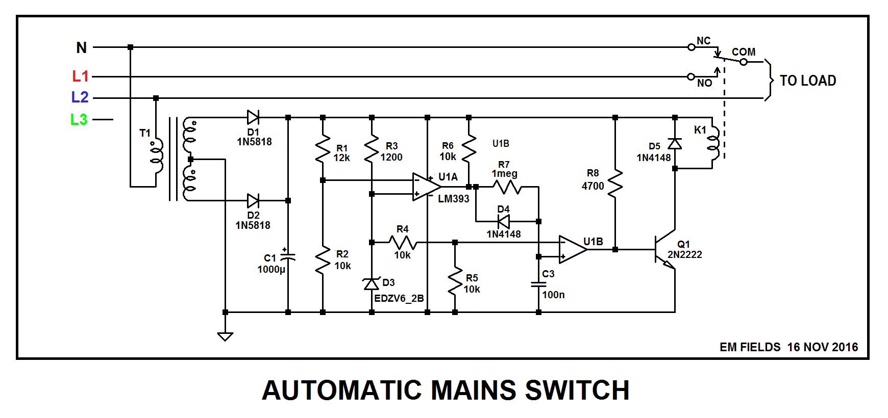
The circuit shown below reflects the complete redesign of the earlier circuit, which resolves issues found when simulating the earlier design, gets rid of the regulator, and incorporates a suggestion made by the OP, Vishal.

THREE PHASE FEED:

With three phase feed, there'll be 230 volts across NEUT and L2 and, through K1's normally closed contact, across the load and the primary of T1.

With 230 volts into T1's primary, the voltage at U1A- will be more positive than the voltage on U1A+, and U1A's output will be low.

U1B is a timer which is used to keep K1 de-energized as the circuit powers up, and with U1A OUT low, C3 will be shorted to ground through D4 and U2B's open collector output. Q1 will be turned OFF, and the relay won't be energized.

R4 and R5 are a voltage divider halving the 6.2 volt reference from D3, and with 3.1 volts on U1B- and about 1 volt on U1B+, U2B OUT will be low, which will short R8 to ground, turning Q1 OFF.

With Q1 off, current can't flow through K1's coil, so the relay will remain in its de-energized state, with COM connected TO NC.

SINGLE PHASE FEED:

With single phase feed, the voltage across NEUT and L2 will drop to about 130 volts, which will cause the voltage at U1A- to be less positive than the voltage on U1A+. That'll cause U1A OUT to go open collector, and C3 will start charging up to the DC supply's positive rail through R6 and R7.

Initially, C3 and U1B+ will be at zero volts and U1B- will be sitting at 3.1 volts, so U1B OUT will be low.

As C3 charges, however, it'll eventually drive U1B+ more and more positive, and when it gets a tiny bit more positive than the 3.1 volts on U2-, U1B OUT will go open collector, diverting the current through R8 from ground into Q1's base, quickly turning K1 ON.

With K1 on, COM will disconnect from NC and will connect to NO, disconnecting the load from NEUTRAL and connecting it across L1 and L2, where it'll be connected across 230 volts.

I've simulated the circuit and it seems to work nicely, and I've posted the LTspice circuit list after the graphic so you can play with the circuit if you want to. Enjoy! :)

If you don't have LTspice it's available, free, here.
enter image description here

Version 4
SHEET 1 2276 2100
WIRE 1744 272 -32 272
WIRE 1872 272 1824 272
WIRE 2048 272 1872 272
WIRE -32 352 -32 272
WIRE 16 352 -32 352
WIRE 128 352 96 352
WIRE 224 352 128 352
WIRE 528 352 304 352
WIRE 1808 352 1808 320
WIRE 240 400 192 400
WIRE 1760 400 1760 320
WIRE 1920 400 1760 400
WIRE 288 448 288 400
WIRE -32 512 -32 352
WIRE 16 512 -32 512
WIRE 112 512 96 512
WIRE 384 512 112 512
WIRE 528 512 528 352
WIRE 528 512 464 512
WIRE 1744 512 528 512
WIRE 1872 512 1872 272
WIRE 1872 512 1824 512
WIRE 2048 528 2048 272
WIRE 400 560 352 560
WIRE 448 608 448 560
WIRE 1808 608 1808 560
WIRE 1920 608 1920 400
WIRE 1920 608 1808 608
WIRE -32 736 -32 512
WIRE 16 736 -32 736
WIRE 128 736 96 736
WIRE 224 736 128 736
WIRE 528 736 304 736
WIRE 192 784 192 400
WIRE 240 784 192 784
WIRE 288 832 288 784
WIRE -32 912 -32 736
WIRE 16 912 -32 912
WIRE 128 912 96 912
WIRE 384 912 128 912
WIRE 528 912 528 736
WIRE 528 912 464 912
WIRE 560 912 528 912
WIRE 2048 912 2048 608
WIRE 2048 912 560 912
WIRE 352 960 352 560
WIRE 400 960 352 960
WIRE 560 976 560 912
WIRE 448 1024 448 960
WIRE 192 1072 192 784
WIRE 352 1072 352 960
WIRE 752 1104 640 1104
WIRE 864 1104 816 1104
WIRE 944 1104 864 1104
WIRE 1056 1104 944 1104
WIRE 1184 1104 1056 1104
WIRE 1264 1104 1184 1104
WIRE 1520 1104 1264 1104
WIRE 1616 1104 1520 1104
WIRE 1760 1104 1760 560
WIRE 1760 1104 1616 1104
WIRE 944 1136 944 1104
WIRE 1056 1136 1056 1104
WIRE 1264 1136 1264 1104
WIRE 560 1152 560 1056
WIRE 1760 1184 1760 1104
WIRE 192 1200 192 1152
WIRE 352 1200 352 1152
WIRE 640 1200 640 1184
WIRE 720 1200 640 1200
WIRE 640 1216 640 1200
WIRE 1616 1216 1616 1104
WIRE 1184 1232 1184 1104
WIRE 944 1248 944 1216
WIRE 1152 1248 944 1248
WIRE 1264 1264 1264 1216
WIRE 1264 1264 1216 1264
WIRE 1296 1264 1264 1264
WIRE 1328 1264 1296 1264
WIRE 1440 1264 1408 1264
WIRE 1056 1280 1056 1216
WIRE 1152 1280 1056 1280
WIRE 592 1296 592 1104
WIRE 608 1296 608 1104
WIRE 752 1296 640 1296
WIRE 864 1296 864 1104
WIRE 864 1296 816 1296
WIRE 1760 1328 1760 1264
WIRE 1920 1328 1920 608
WIRE 1920 1328 1760 1328
WIRE 1296 1344 1296 1264
WIRE 1328 1344 1296 1344
WIRE 1440 1344 1440 1264
WIRE 1440 1344 1392 1344
WIRE 1760 1360 1760 1328
WIRE 1520 1376 1520 1104
WIRE 864 1392 864 1296
WIRE 944 1392 944 1248
WIRE 1056 1392 1056 1280
WIRE 1088 1392 1056 1392
WIRE 1248 1392 1168 1392
WIRE 1488 1392 1248 1392
WIRE -32 1408 -32 912
WIRE 32 1408 -32 1408
WIRE 560 1408 560 1232
WIRE 560 1408 32 1408
WIRE 592 1408 560 1408
WIRE 720 1408 720 1200
WIRE 720 1408 672 1408
WIRE 1616 1408 1616 1296
WIRE 1616 1408 1552 1408
WIRE 1696 1408 1616 1408
WIRE 1440 1424 1440 1344
WIRE 1488 1424 1440 1424
WIRE 1248 1440 1248 1392
WIRE 1056 1456 1056 1392
WIRE 1440 1456 1440 1424
WIRE 720 1552 720 1408
WIRE 864 1552 864 1456
WIRE 864 1552 720 1552
WIRE 944 1552 944 1472
WIRE 944 1552 864 1552
WIRE 1056 1552 1056 1520
WIRE 1056 1552 944 1552
WIRE 1184 1552 1184 1296
WIRE 1184 1552 1056 1552
WIRE 1248 1552 1248 1520
WIRE 1248 1552 1184 1552
WIRE 1440 1552 1440 1520
WIRE 1440 1552 1248 1552
WIRE 1520 1552 1520 1440
WIRE 1520 1552 1440 1552
WIRE 1760 1552 1760 1456
WIRE 1760 1552 1520 1552
WIRE 720 1648 720 1552
FLAG 720 1648 0
FLAG 128 912 L2325
FLAG 112 512 L1325
FLAG 32 1408 NEUT
FLAG 1808 352 0
FLAG 128 352 L1184
FLAG 128 736 L2184
FLAG 288 448 0
FLAG 448 608 0
FLAG 288 832 0
FLAG 448 1024 0
FLAG 192 1200 0
FLAG 352 1200 0
SYMBOL ind2 544 1136 R0
WINDOW 0 -29 40 Left 2
WINDOW 3 -33 65 Left 2
SYMATTR InstName L1
SYMATTR Value 17
SYMATTR Type ind
SYMBOL ind2 656 1088 M0
WINDOW 0 -40 48 Left 2
WINDOW 3 -49 77 Left 2
SYMATTR InstName L2
SYMATTR Value 50m
SYMATTR Type ind
SYMBOL ind2 656 1200 M0
WINDOW 0 -37 42 Left 2
WINDOW 3 -47 70 Left 2
SYMATTR InstName L3
SYMATTR Value 50m
SYMATTR Type ind
SYMBOL schottky 752 1120 R270
WINDOW 0 32 32 VTop 2
WINDOW 3 0 32 VBottom 2
SYMATTR InstName D1
SYMATTR Value 1N5818
SYMATTR Description Diode
SYMATTR Type diode
SYMBOL polcap 848 1392 R0
WINDOW 0 -39 36 Left 2
WINDOW 3 -54 62 Left 2
SYMATTR InstName C1
SYMATTR Value 1000µ
SYMBOL res 928 1120 R0
WINDOW 0 47 46 Left 2
WINDOW 3 41 77 Left 2
SYMATTR InstName R3
SYMATTR Value 12k
SYMBOL res 928 1376 R0
WINDOW 0 50 41 Left 2
WINDOW 3 43 70 Left 2
SYMATTR InstName R4
SYMATTR Value 10k
SYMBOL schottky 752 1312 R270
WINDOW 0 32 32 VTop 2
WINDOW 3 0 32 VBottom 2
SYMATTR InstName D2
SYMATTR Value 1N5818
SYMATTR Description Diode
SYMATTR Type diode
SYMBOL res 1600 1200 R0
WINDOW 0 -44 27 Left 2
WINDOW 3 -60 57 Left 2
SYMATTR InstName R5
SYMATTR Value 4700
SYMBOL npn 1696 1360 R0
SYMATTR InstName Q1
SYMATTR Value 2N2222
SYMBOL res 1776 1280 R180
WINDOW 0 36 76 Left 2
WINDOW 3 36 40 Left 2
SYMATTR InstName R6
SYMATTR Value 160
SYMBOL Comparators\\LT1017 1184 1264 R0
SYMATTR InstName U1
SYMBOL res 1040 1120 R0
SYMATTR InstName R2
SYMATTR Value 1200
SYMBOL zener 1072 1520 R180
WINDOW 0 -39 36 Left 2
WINDOW 3 -105 -1 Left 2
SYMATTR InstName D3
SYMATTR Value EDZV6_2B
SYMBOL Comparators\\LT1017 1520 1408 R0
SYMATTR InstName U2
SYMBOL res 1248 1120 R0
WINDOW 0 40 48 Left 2
WINDOW 3 37 82 Left 2
SYMATTR InstName R7
SYMATTR Value 10k
SYMBOL cap 1424 1456 R0
SYMATTR InstName C3
SYMATTR Value 100n
SYMBOL res 1424 1248 R90
WINDOW 0 -33 58 VBottom 2
WINDOW 3 -28 61 VTop 2
SYMATTR InstName R8
SYMATTR Value 1meg
SYMBOL diode 1392 1328 R90
WINDOW 0 0 32 VBottom 2
WINDOW 3 32 32 VTop 2
SYMATTR InstName D4
SYMATTR Value 1N4148
SYMBOL res 1184 1376 R90
WINDOW 0 0 56 VBottom 2
WINDOW 3 32 56 VTop 2
SYMATTR InstName R9
SYMATTR Value 10k
SYMBOL res 1232 1424 R0
SYMATTR InstName R10
SYMATTR Value 10k
SYMBOL Misc\\signal 112 512 R90
WINDOW 3 24 104 Invisible 2
WINDOW 123 0 0 Left 2
WINDOW 39 0 0 Left 2
WINDOW 0 52 27 VRight 2
SYMATTR Value SINE(0 325 50 0 0 120)
SYMATTR InstName V325A
SYMBOL Misc\\signal 112 912 R90
WINDOW 3 24 104 Invisible 2
WINDOW 123 0 0 Left 2
WINDOW 39 0 0 Left 2
WINDOW 0 52 26 VRight 2
SYMATTR Value SINE(0 325 50 0 0 240)
SYMATTR InstName V325B
SYMBOL Misc\\signal 112 352 R90
WINDOW 3 24 104 Invisible 2
WINDOW 123 0 0 Left 2
WINDOW 39 0 0 Left 2
WINDOW 0 58 22 VRight 2
SYMATTR Value SINE(0 184 50 0 0 120)
SYMATTR InstName V184A
SYMBOL Misc\\signal 112 736 R90
WINDOW 3 24 104 Invisible 2
WINDOW 123 0 0 Left 2
WINDOW 39 0 0 Left 2
WINDOW 0 60 22 VRight 2
SYMATTR Value SINE(0 184 50 0 0 240)
SYMATTR InstName V184B
SYMBOL res 688 1392 R90
WINDOW 0 0 56 VBottom 2
WINDOW 3 32 56 VTop 2
SYMATTR InstName R1
SYMATTR Value 1G
SYMBOL sw 1840 272 M270
WINDOW 0 21 189 VLeft 2
WINDOW 3 52 172 VLeft 2
SYMATTR InstName S325NC
SYMBOL res 2064 624 R180
WINDOW 0 36 76 Left 2
WINDOW 3 36 40 Left 2
SYMATTR InstName R11
SYMATTR Value 100
SYMBOL sw 1840 512 M270
WINDOW 0 20 188 VLeft 2
WINDOW 3 50 168 VLeft 2
SYMATTR InstName S325NO
SYMBOL res 544 960 R0
SYMATTR InstName R12
SYMATTR Value 1
SYMBOL sw 320 352 M270
WINDOW 0 -27 12 VLeft 2
WINDOW 3 26 15 VLeft 2
SYMATTR InstName S3
SYMBOL sw 480 512 M270
WINDOW 0 -27 12 VLeft 2
WINDOW 3 26 15 VLeft 2
SYMATTR InstName S4
SYMBOL sw 320 736 M270
WINDOW 0 -27 12 VLeft 2
WINDOW 3 26 15 VLeft 2
SYMATTR InstName S5
SYMBOL sw 480 912 M270
WINDOW 0 -27 12 VLeft 2
WINDOW 3 26 15 VLeft 2
SYMATTR InstName S6
SYMBOL voltage 192 1056 R0
WINDOW 3 24 96 Invisible 2
WINDOW 123 0 0 Left 2
WINDOW 39 0 0 Left 2
SYMATTR InstName V5
SYMATTR Value PULSE(0 1 1 1m 1m 1)
SYMBOL voltage 352 1056 R0
WINDOW 3 24 96 Invisible 2
WINDOW 123 0 0 Left 2
WINDOW 39 0 0 Left 2
SYMATTR InstName V6
SYMATTR Value PULSE(0 1 5 1m 1m 1)
TEXT 744 1632 Left 2 !K L1 L2 L3 1
TEXT 736 1576 Left 2 !.tran 10 startup uic
TEXT 736 1600 Left 2 !.model SW SW(Ron=.01 Roff=1G Vt=0.5 Vh=0)
TEXT 1776 1256 Left 2 ;RELAY COIL
TEXT 1776 1288 Left 2 ;RESISTANCE
TEXT 592 1080 Left 2 ;T1
TEXT 352 1472 Left 2 ;R1 AND R12 ARE FOR SIM ONLY
\$\endgroup\$
16
  • \$\begingroup\$ Thanks for the answer. I think it will definitely work. But I would like to ask you 2 questions. First Question is: Where should I connect the Non-inverting Input of Op-amp LT6703-2 and second question is: What is the need of upper circuit? Yes, you have mentioned that it will energize the Relay. But Can I ask you that What happens if I connect the other end of K1 to the output of D3 instead of 7812's output? \$\endgroup\$
    – Vishal
    Commented Nov 12, 2016 at 17:16
  • \$\begingroup\$ @Vishal: That's three questions. ;) The LT6703-2 isn't an opamp, it's a voltage comparator and its non-inverting input is connected to an internal 400 millivolt reference. Here's a link to its data sheet As for the rest of it, it sounds like it might be a good idea, but you need to look at the relay's minimum pull-in voltage and maximum coil power dissipation specifications with respect to the different voltages appearing across NEUT and L2. Have you chosen a relay yet? \$\endgroup\$
    – EM Fields
    Commented Nov 12, 2016 at 18:30
  • \$\begingroup\$ No, I haven't chosen one. \$\endgroup\$
    – Vishal
    Commented Nov 12, 2016 at 18:32
  • \$\begingroup\$ @Vishal: Do you know how to go about choosing one? \$\endgroup\$
    – EM Fields
    Commented Nov 12, 2016 at 18:49
  • \$\begingroup\$ No, I don't know. Will you teach me? \$\endgroup\$
    – Vishal
    Commented Nov 12, 2016 at 18:55
0
\$\begingroup\$

An electronic solution that meets your requirement can be provided if desired, but you should be able to use a simple relay switch with minimal electronics.

ie Without extra logic circuitry provide a relay that operates when 400VAC is applied but not when 230 VAC is applied (or 230/180 if connected phase to neutral) and switch connection with this relay.

The relay could use a 400v:12V (say) transformer as you have shown to allow use of a 12 V coil relay. If you use a bridge rectifier (getting) more complex :-) ) you can use a DC relay. Then you can adjust pull-in/dropout voltage easily.

Adding a series resistor in the coil circuit raises pullin voltage and dropout voltage but possibly not the latter by enough.

Adding a zener diode in series with the DC feed provides a greater difference.
eg say input is 440:230V as power switches.
Convert this with transformer to 12V:6.3V.
Convert to DC giving about 15V:8V say.
Adding a series zener of say ~= 8V means
a relay coil will see about (15-8):(8-8)
~= 7V:0V
so a 6V coil relay will switch well.

NB: Is it really 440V:230V or 400V:230V?

\$\endgroup\$
1
  • \$\begingroup\$ Can you please post a diagram? \$\endgroup\$
    – Vishal
    Commented Nov 12, 2016 at 14:00

Your Answer

By clicking “Post Your Answer”, you agree to our terms of service and acknowledge you have read our privacy policy.

Not the answer you're looking for? Browse other questions tagged or ask your own question.