Consider approaching this problem differently.
Rather than brute forcing your way by trying to source extremely precise and stable (thus expensive) shunt resistors, settle for a middle ground constituting of medium precision and medium stability.
If the projects you are doing involve some kind of digital microprocessor responsible for measuring or producing a digital readout then your in luck. If not consider using one! Software can fix this to a large extent.
Out of the box inaccuracies in the resistor are not going to be a problem. You simply need to measure it to the required precision and apply the corrective action in software.
Now temperature stability is of more concern because it does not involve a simple one point fix and can vary across resistors. However, as you say you are a hobbyist this should also not be a problem.
Start by measuring the drift of your resistor and tabulate a list of Power Dissipation (,temperature,current) vs Drift. Feed that data into a spreadsheet program like Excel, perform regression, extract the coefficients and apply the corrective action in software!
You can get amazing accuracy and stability with this method without spending a fortune!
EDIT:
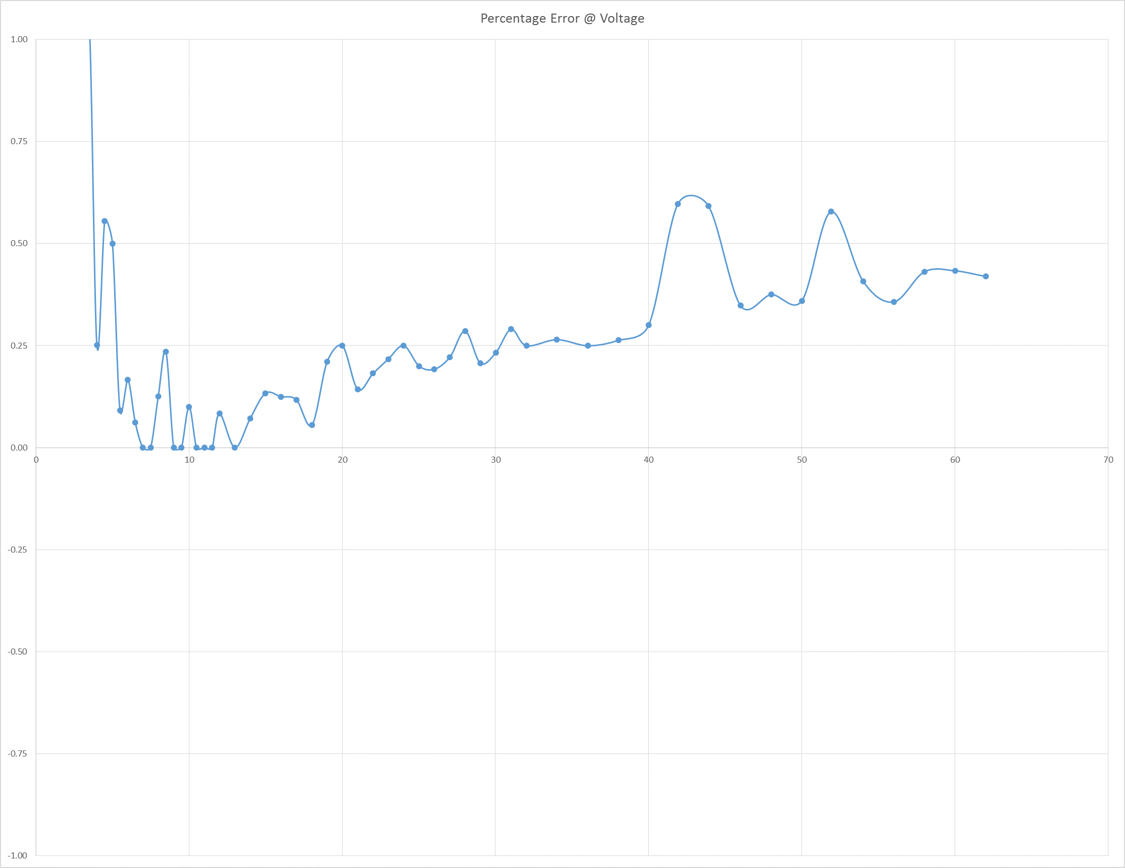
Here is an slightly unrelated example of a multipoint type calibration i did recently to illustrate the results of calibrating to get your way out of non ideal components. In the example Im using an ADC that exhibits substantial drift at higher voltages measured:

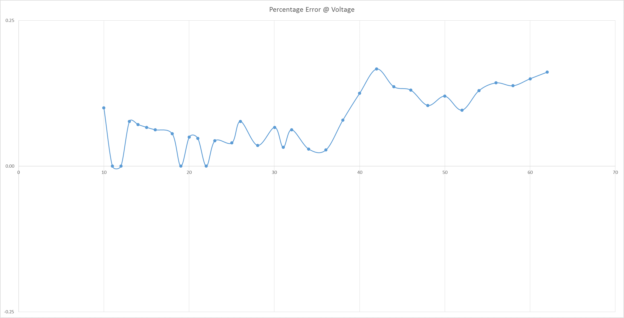
Here is the same ADC after I tabulated the error and performed regression and the software fix:


