4
\$\begingroup\$

I am looking for the simplest electronic solution to be contained in boxes B1 and B2 so that when the switch SW is toggled, a signal (free choice) should be carried across the AC power lines (residential 110/220V) to B2 where it should be detected and converted to a small voltage meant to feed some input GPIO pin of a microcontroller.

In other words, the uC should be aware whenever the switch gets toggled, provided the configuration. B1 and B2 are some feet apart and the circuit is also used for other consumers, therefore no huge voltage or current spikes can be used unless filtered by B2. The carried signal can be of any kind as far as B1 can generate it and B2 can detect (and further cancel) it. I hope for an easy solution, not involving additional uC or heavy signal modulation processing, if possible.

LE: based on the provided answers I want to stress out the need of the simplest solution to send/receive a "sign" of any kind over the power lines. I don't need to de/modulate data, a fair voltage spike generated by B1 that can be detected and filtered out in B2 would be enough for the "sign" I need, if possible. I'd rather avoid uC and heavy processing in B1, maybe just in B2.

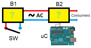
scheme

\$\endgroup\$
3
  • 1
    \$\begingroup\$ Google Riva PLC and IEEE1901.2. \$\endgroup\$
    – skvery
    Commented Mar 16, 2017 at 21:13
  • \$\begingroup\$ Is this local to a house, street, etc ...how far do you want this signal to go. Potential regulation problems if you want this beyond a house, the utilities don't like you using their wires as a communications channel. The power line is a very low impedance, you need considerable power at very low frequencies to get through all the roadblocks such as transformers and power factor correction blocks. Perhaps describe what you are actually trying to achieve and someone could help you. \$\endgroup\$ Commented Mar 16, 2017 at 21:14
  • \$\begingroup\$ All this happens inside a house, a room actually. There's a switch and I can insert B1 before it in the wall box and a few feet away (no consumers yet on the circuit) I have access to the power line wires where I can hook B2. Is here that I need to know each time the switch is toggled. The power lines further feed some residential consumers. \$\endgroup\$
    – i2r
    Commented Mar 16, 2017 at 21:28

3 Answers 3

2
\$\begingroup\$

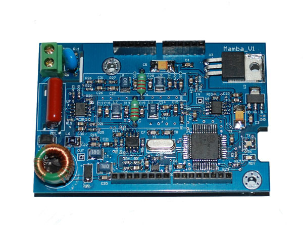
You were not clear if you wanted to design your own or buy an off the shelf product. Either way I doubt you will do better than this cost wise.

Powerline Communication Shield for Arduino

LINK Product Information

LINK to buy Shield $50

They also have a Powerline Communication Module $29

Powerline Communication Shield for Arduino


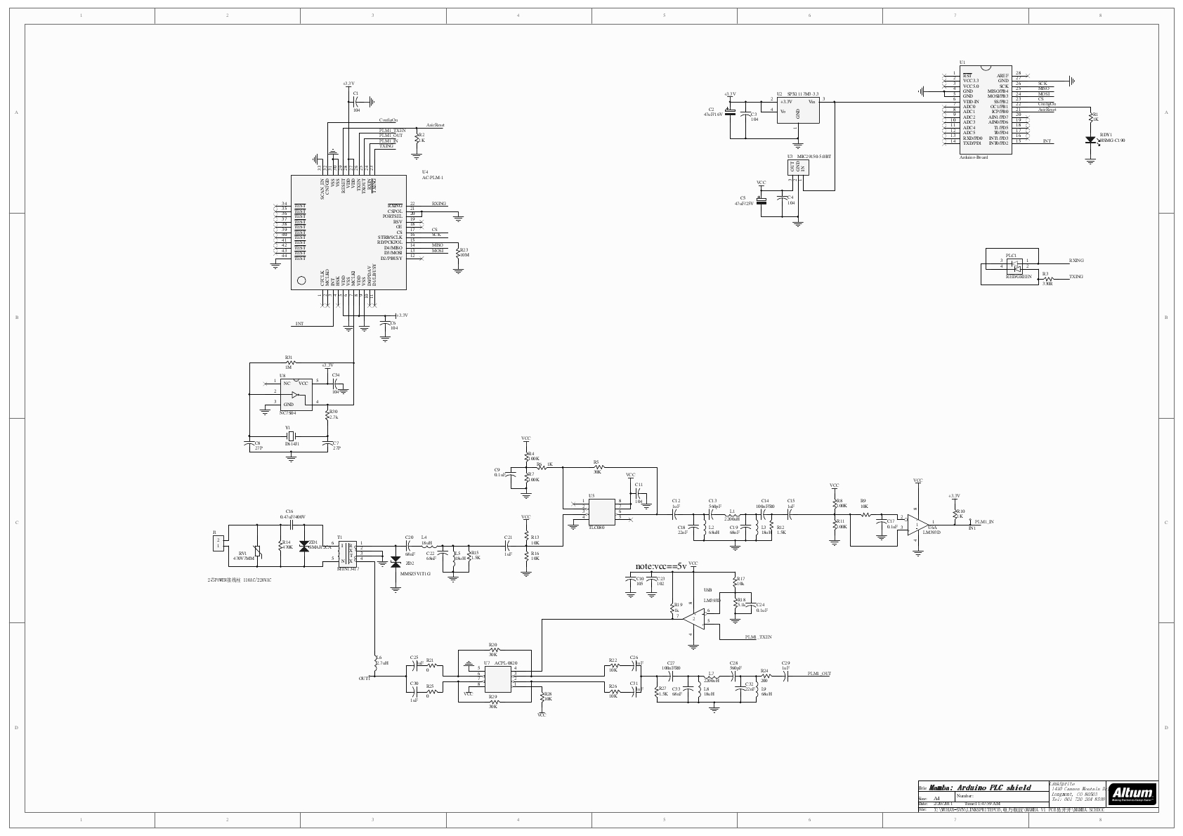
Or build your own from the schematics (PDF)


Powerline Modem Schematic

\$\endgroup\$
0
\$\begingroup\$

So the first thing that came to mind was those ethernet over power boxes (not to be confused with Power over Ethernet). Unfortunately they seem to be black magic with regard to tracking down a good schematic, however the process was described as:

"Such products are based on a standard called HPAV - HomePlug AV. They essentially couple the AC line with the digital baseband signal. The AC line has a frequency of 50-60Hz, while the digital communication happens between 2Mhz & 50Mhz. The upper limit is determined by the flavor of HPAV used. On the receiver, the AC interference is filtered out and the digital signal is demodulated. - https://www.quora.com/In-a-nutshell-how-do-ethernet-over-power-line-adapters-work

This is appears to be what you are trying to do. In searching I found the following site about making a WiFi switch for an electronic device, so depending on how tight your constraints are either solution may work...

http://www.esp8266-projects.com/2015/03/esp8266-cbdb-web-power-switch-for-mains.html

Whatever you end up going with, be careful since it is mains and try to have someone else around just in case.

\$\endgroup\$
0
\$\begingroup\$

If you are willing to take a different approach, then there is a simpler and inexpensive way to do all this. You can install two esp8266 modules - one each in B1 and B2. Esp in B1 will detect the switch state and transfer the information to B2 over wifi. Follow this answer to learn how to sense ac using a micro-controller:

https://electronics.stackexchange.com/a/208596/68606

The answer was written for R-Pi but it will hold true for any micro-controller.

\$\endgroup\$

Your Answer

By clicking “Post Your Answer”, you agree to our terms of service and acknowledge you have read our privacy policy.

Not the answer you're looking for? Browse other questions tagged or ask your own question.