4
\$\begingroup\$

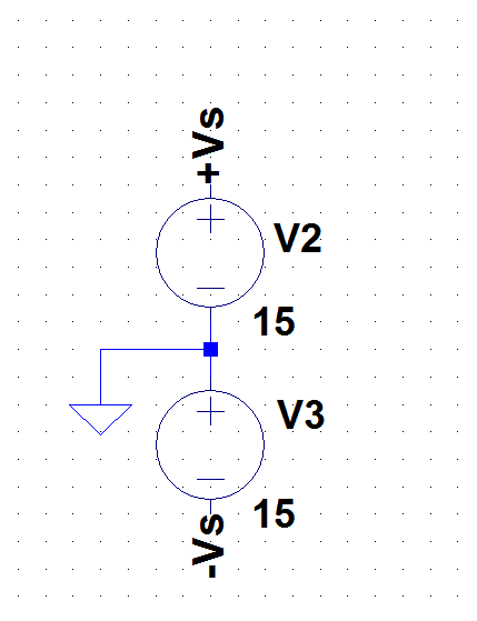
Below is how many people make a +/-15V split-supply in LTspice:

enter image description here

But this takes too much time each time to select 3 components GND and give them values one by one, etc.

So I was wondering if there is a way to copy this topology as a single symbol or create one in LTspice from scratch. The idea is to select a split-supply directly from its own symbol. Does anyone have experience with that? I saw some tutorials how to make symbols but they were about op-amps.

\$\endgroup\$
4
  • \$\begingroup\$ youtube.com/watch?v=uOjkZM3p6Lg \$\endgroup\$
    – Daniel
    Commented Apr 16, 2017 at 16:08
  • \$\begingroup\$ I just open up a previous simulation and copy the whole shebang into a new schematic... \$\endgroup\$
    – uint128_t
    Commented Apr 16, 2017 at 16:20
  • \$\begingroup\$ I do the same sometimes but would be great to have a special symbol for that, just like selecting a single supply. \$\endgroup\$
    – user16307
    Commented Apr 16, 2017 at 16:24
  • \$\begingroup\$ Forgive me but I'm on my cellphone but you should be able create your own user defined elements. Check this website out \$\endgroup\$
    – user103380
    Commented Apr 16, 2017 at 16:51

1 Answer 1

8
\$\begingroup\$

As you draw more and more schematics, you'll probably develop a preference towards uncluttered schematics. You'll find out soon that placing specific components for the supply rails clutters them too much. Even if it's just a single component for a dual split supply, like the one you're looking for.

To avoid this altogether, you can simply define these voltages directly in the same text box where your simulation directives resides. Like this:

V98 VS+ 0 15
V99 VS- 0 -15

** Your simulation directives follow (what's below it's just an example):
.tran 0 100m 0 1m startup

Then use the net names VS+ and VS- all over your schematic as you need them.

NOTE:

The reason for choosing V98 and V99 as names for the source (instead of V1 and V2, for example) is to avoid conflicts when placing source symbols in the schematic. This happens because the schematic editor in LTspice doesn't seem to "observe" device naming in spice directives.

(Thanks go to jonk for pointing this out in the comments, and making this answer a better one).

\$\endgroup\$
4
  • 1
    \$\begingroup\$ This is a really cool way. No need to add supply in the schematics. It would be great to make this directive as a short cut though. \$\endgroup\$
    – user16307
    Commented Apr 16, 2017 at 19:31
  • \$\begingroup\$ Some operating systems allow you to define your own custom keyboard shortcuts. In OS X you could define "split15V" and let the system replace it with the voltage sources definitions. :D But that would be too much, perhaps... \$\endgroup\$ Commented Apr 16, 2017 at 19:51
  • 1
    \$\begingroup\$ Just be careful here. If you then add another voltage supply symbol to the schematic using "F2" for example, then you might get a symbol for V1 or V2 and NOT for V3, as you'd probably want. So just be careful about this possible source for an error. The schematic editor doesn't seem to "observe" device naming in spice directives. \$\endgroup\$
    – jonk
    Commented Apr 16, 2017 at 20:00
  • \$\begingroup\$ Well seen @jonk ! You're absolutely right. I'll update my answer to reflect this. \$\endgroup\$ Commented Apr 16, 2017 at 20:04

Your Answer

By clicking “Post Your Answer”, you agree to our terms of service and acknowledge you have read our privacy policy.

Not the answer you're looking for? Browse other questions tagged or ask your own question.