0
\$\begingroup\$

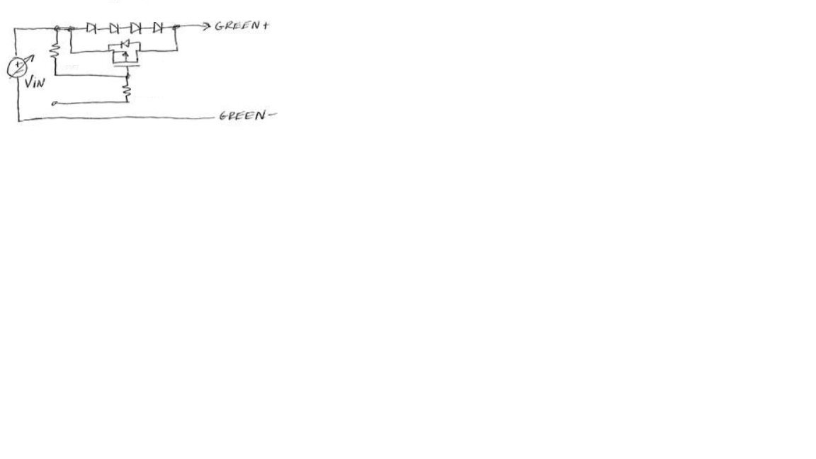
I am driving green LED in series with a boost converter and unfortunately my input voltage (24VDC) turns my LED string on slightly even when my manually controlled boost converter is not boosting the voltage. I'm thinking that adding 4 diodes in series with my LED string will be enough to increase the forward voltage so it doesn't turn on until I begin to increase my boost converter voltage past 30V. I'd also like to turn a PFET on so that I can bypass the 4 diodes once I begin increasing the voltage above 24. Any ideas on how to wire the PFET so that when VIN goes above 30VDC, the bypass PFET turns on?

Or any other ideas on how to prevent my LED string from turning on when I'm at 24V?

Thanks in advance!

enter image description here

\$\endgroup\$
4
  • \$\begingroup\$ why not simply add an N-MOSFET "enable" transistor between the LEDs & GND? Pos voltage to MOSFET gate allows current to flow, and GND voltage to MOSFET gate stops current from flowing...problem solved ;) \$\endgroup\$ Commented Apr 25, 2017 at 0:44
  • \$\begingroup\$ What Robherc said is good, and the best way to go unless for some reason you can't put a switch between LED's and ground. If that is the case, just use a single PMOS in series with the green LED's. No diodes needed. Use a low-cost logic level NMOS or even an NPN BJT to pull the PMOS gate low when you want to enable the LED's. \$\endgroup\$
    – user57037
    Commented Apr 25, 2017 at 3:47
  • \$\begingroup\$ Make sure you never operate the boost converter into an open circuit. Voltage can climb very high and cause components to fail. \$\endgroup\$
    – user57037
    Commented Apr 25, 2017 at 3:51
  • \$\begingroup\$ There will be significant power dissipation during dimming in a series nfet compared to a switching controller. \$\endgroup\$ Commented Apr 26, 2017 at 19:08

1 Answer 1

1
\$\begingroup\$

First, you're making this way too complicated.

Your boost converter should be configured as a current source, having a current sensing resistor provide feedback to the boost circuit to regulate current through your LED string. The LEDs themselves will regulate/limit their voltage drop.

The boost converter should have an Enable/Disable pin for turning the LEDs on/off.

\$\endgroup\$
1
  • \$\begingroup\$ The boost converter is already setup as a current source with a current feedback sense. The issue that I am having is that my input voltage is too near the turn-on voltage of the LED array. So even when the boost converter is disabled, the input voltage is making its way directly through the inductor and turning on the LED array. Hence, the diodes in series to increase the turn-on voltage of the array. And the need for a bypass to the diodes \$\endgroup\$ Commented Apr 26, 2017 at 19:13

Your Answer

By clicking “Post Your Answer”, you agree to our terms of service and acknowledge you have read our privacy policy.

Not the answer you're looking for? Browse other questions tagged or ask your own question.