0
\$\begingroup\$

In a boost converter, what is the factor that determines whether the power supply (dc-dc converter) will be in the CCM, BCM or DCM mode?

Because, I have an LED Driver A80604. And I am trying to calculate the inductor value for it.

Input Voltage = 9.5V to 16V

LED string = 9 LEDs (each Vf of 3.1V and If=0.3A)

Output voltage = 30V

Output Current = 300mA

In this case, I have been following the design example from page 35.

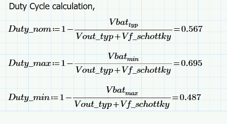
I have got to this point :

Vout_typ = 30.64V & Vf_schottky=0.52V. Vbat = 9.5V, 13.5V & 16V (Min, typ and Max)

enter image description here

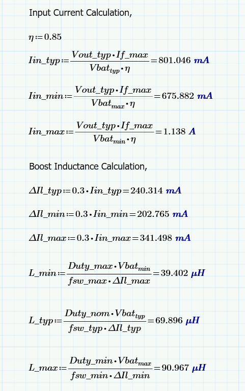
enter image description here

Are my above calculations, right?

My questions:

  1. What is the factor that determines whether the power supply (dc-dc converter) will be in the CCM, BCM or DCM mode?

  2. What is the required inductor value that I need to choose for this application which requires constant current for the LEDs?

\$\endgroup\$
2
  • \$\begingroup\$ I left you an interactive calculator link on your previous question in comments. You should enter a few values and see what you get. Operating frequency is needed. \$\endgroup\$
    – Andy aka
    Commented Apr 1, 2021 at 11:23
  • \$\begingroup\$ Operating frequency is 455kHz.. Can you please tell me what deternines the CCM and other modes \$\endgroup\$
    – user220456
    Commented Apr 1, 2021 at 11:44

1 Answer 1

1
\$\begingroup\$

What is the factor that determines whether the power supply (dc-dc converter) will be in the CCM, BCM or DCM mode?

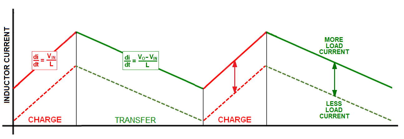
The dominant factor is load current. If the load current goes beyond a certain value the boost converter will operate in continuous conduction mode: -

enter image description here

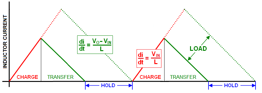
On lighter loads the boost converter will operate in discontinuous conduction mode: -

enter image description here

And, at exactly one point, DCM and CCM look the same - this is called boundary conduction mode.

What is the required inductor value that I need to choose for this application which requires constant current for the LEDs?
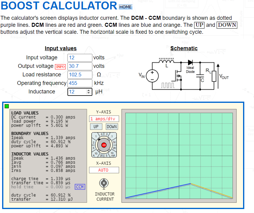
If you want to run in CCM (probably the likely choice) then if the input voltage is 12 volts, the output voltage is 30 volts, the output current is 300 mA and the operating frequency is 455 kHz then, the minimum inductance value is around 12 μH: -

enter image description here

Note that I set the output voltage to be 30.7 volts to accommodate the forward drop of a real diode. The dotted lines in the above graph show the BCM point. If the converter current waveform fell below that BCM line, you'd be in DCM.

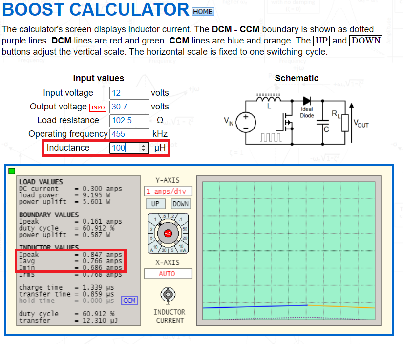
However, that gives over 1.3 amps of input supply ripple current and you may choose to make the inductor a lot bigger such as 100 μH: -

enter image description here

Now, the ripple current is 0.847 amps minus 0.686 amps = 161 mA

I expect somewhere between the two will be the right answer but, you can use the interactive boost tool to try out different scenarios.

Your value range from 39 μH to 91 μH is going to be about right. My low end value of 12 μH might cause the boost circuit to drop into DCM mode on a lower load current and sometimes, that can cause stability problems.

\$\endgroup\$
23
  • \$\begingroup\$ Thank you for the detailed answer. 1.3A of inductor ripple current? In my calculations, it is less. What am I thinking wrong here? \$\endgroup\$
    – user220456
    Commented Apr 1, 2021 at 12:00
  • 1
    \$\begingroup\$ @Newbie correct and, if you carry on making it lower, the converter will drop from CCM to DCM. \$\endgroup\$
    – Andy aka
    Commented Apr 1, 2021 at 12:16
  • 1
    \$\begingroup\$ @Newbie I tried to make the website as clear as I could so, given it is my website, if you want, you can conduct this conversation away from SE.EE by contacting me on my EE email (info@ link on this page). It's a useful exercise for me because it might help me improve my website. \$\endgroup\$
    – Andy aka
    Commented Apr 1, 2021 at 17:26
  • 1
    \$\begingroup\$ You should concentrate on understanding why the slopes of the inductor's current are related to input voltage and output voltage - that is crucial and that bit may take a time to sink in because inductors are not everyone's favourite component. \$\endgroup\$
    – Andy aka
    Commented Apr 1, 2021 at 17:30
  • 1
    \$\begingroup\$ It's a generic tool but assumes perfection in power transfer and zero diode losses hence why I made the output voltage 30.7 volts so that the forward drop of the diode is accounted for. \$\endgroup\$
    – Andy aka
    Commented Apr 1, 2021 at 17:42

Your Answer

By clicking “Post Your Answer”, you agree to our terms of service and acknowledge you have read our privacy policy.