0
\$\begingroup\$

I have this (run) capacitor with 4 terminals for a sewing machine motor. I have fixed some minor issues but now I realize I don't know how the wiring was before. I don't find an explanation for the scheme on the back of it anywhere so I post the image here Capacitor back
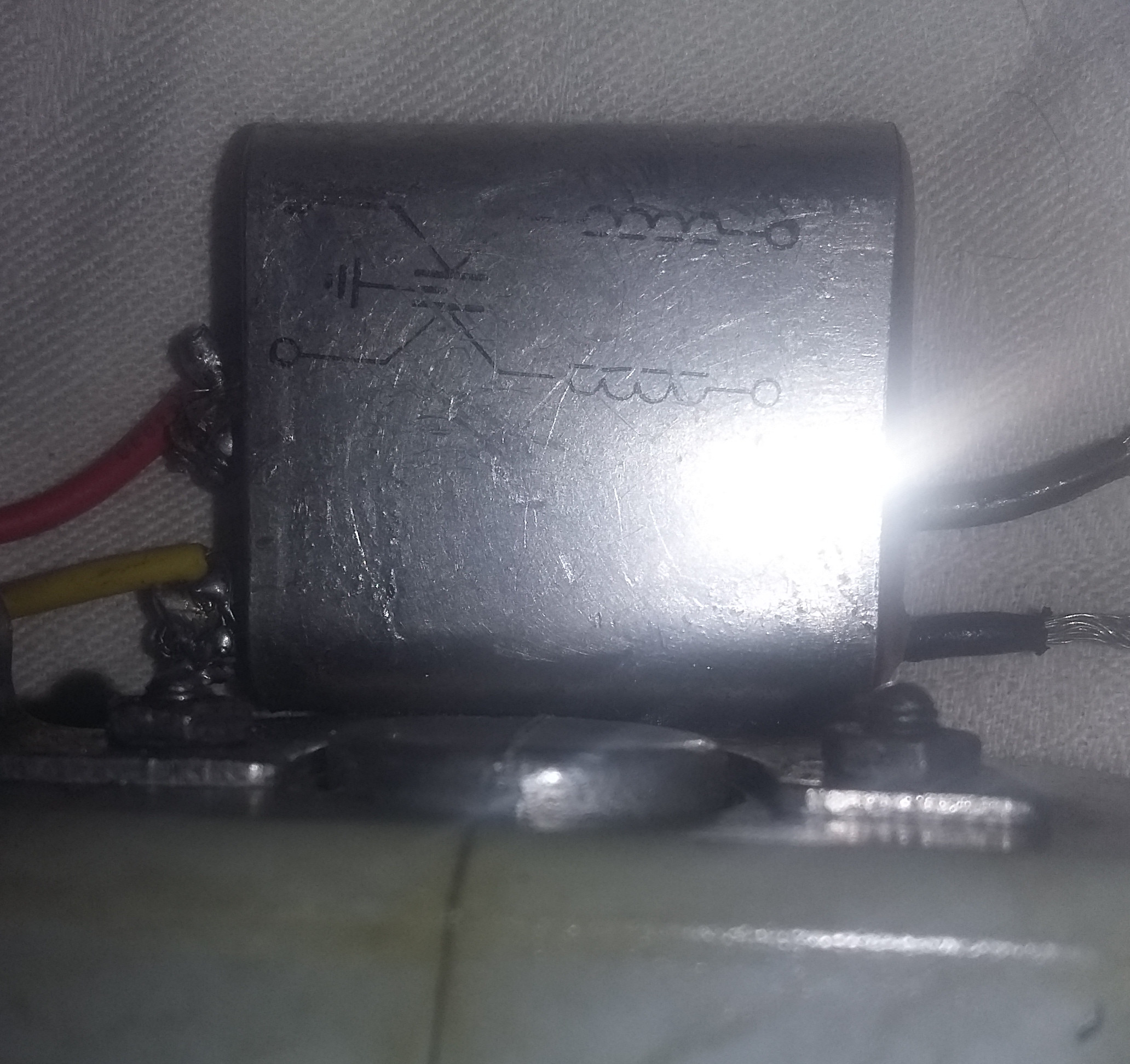
Two terminals should connect the motor and the others two the pedal.

A front image, too, in case it helps: Capacitor front
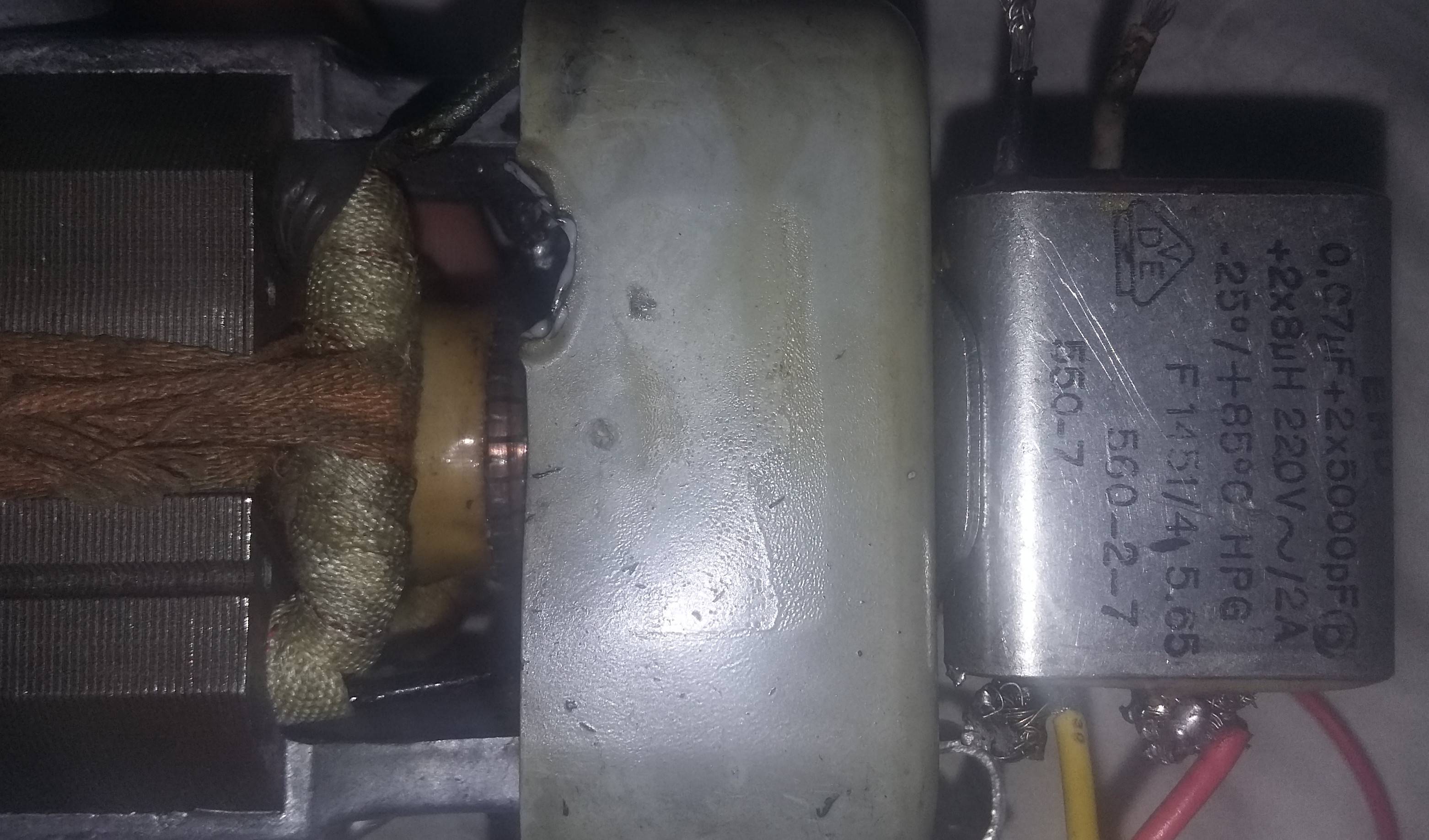
I have not found anything about this model/type anywhere

\$\endgroup\$

1 Answer 1

3
\$\begingroup\$

This is not a capacitor but a mains input filter/Power line filter (which, as shown on the little schematic that is printed on top of it contains two capacitors and a common-mode choke) It's placed in series with the input - one side has the power line, other side has the device being powerd. If you are still not sure, I suggest googleing the topic.

\$\endgroup\$
2
  • \$\begingroup\$ I see. Red and yellow to input and black wires to coils. Thanks for the explanation and correction \$\endgroup\$
    – ali
    Commented May 14, 2017 at 9:36
  • \$\begingroup\$ I guess the motor can run without it, too. It blew up (old, I guess) and cannot find another one \$\endgroup\$
    – ali
    Commented May 23, 2017 at 7:06

Your Answer

By clicking “Post Your Answer”, you agree to our terms of service and acknowledge you have read our privacy policy.

Not the answer you're looking for? Browse other questions tagged or ask your own question.