1
\$\begingroup\$

Problem 4.4 from Microelectronics circuits by Sedra and Smith

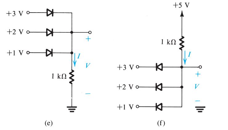
Find voltage V and current I. As per the book, answer is (e) 3 mA, +3 V; (f) 4 mA, +1V . But I don't know how we got there.

Edit: For figure (e):

I understand that diode connected to +3V supply will be forward biased because the anode of this diode is connected to maximum positive voltage in the circuit. But, I don't understand why diodes connected to +2V and +1V is reverse biased.

For figure (f):

Diode connected to +1V supply is forward biased because cathode of this diode is connected to least positive voltage in the circuit.But, I don't understand why diode connected to +2V and +3V is reverse biased.

\$\endgroup\$
2
  • \$\begingroup\$ Welcome to the site but we don't do your homework for you. If you edit your question to explain what you do and don't understand you will get good help. \$\endgroup\$
    – Transistor
    Commented Jun 10, 2017 at 11:04
  • 1
    \$\begingroup\$ Well, this is not my homework I'm just brushing up my knowledge in electronics devices. And I've made the edit to the question what I do and don't understand. \$\endgroup\$
    – Saurabh
    Commented Jun 10, 2017 at 12:02

2 Answers 2

2
\$\begingroup\$

You have the answer already and have asked for guidance ("But I don't know how we got there"), which is all I can give for homework questions...

Your question uses 'perfect' diodes, so no voltage drop and no leakage currents amongst other things.

Perfect diodes do not conduct when they are reverse-biased. Therefore any path that has a reverse-biased diode is open-circuit. When you're assessing the circuit, pretend that reverse-biased diode paths are not there.

Look at each diode in turn. Seeing the voltage it puts onto the resistor bottom-end, consider the effect on the other diodes.

This should take you most of the way to the answer. Then its just Ohm's Law at the end.

\$\endgroup\$
2
\$\begingroup\$

After thinking for a while I came up with the following explanation for the behaviour of the given circuit.

For figure (e):

Current from +3V supply, apart from flowing through 1k ohm resistor also try to charge +2V and +1V supply. But for this to happen current has to flow from cathode to anode of diodes connected to +2V and +1V supply which makes them reverse biased. Since now +2V and +1V supply are out of the circuit we can easily obtained the voltage and current in the circuit.

For figure (f):

Current from +5V supply will try to charge +3V, +2V and +1V supply through 1k ohm resistor. We know that current follow least resistance path or conversely we can say that a circuit is try to draw maximum current from the source. Maximum potential difference exist between +5V and +1V, hence maximum current will flow from this path. Since diode connected form +1V supply is forward biased, this will make the potential of anode of diodes connected form +2V and +3V equal to +1V which will make them reverse biased. Now current and voltages in the circuit can be easily calculated.

\$\endgroup\$
1
  • 1
    \$\begingroup\$ You've got it! You would see a similar situation in a hydraulic or pneumatic circuit if you replace the voltage sources with pressure sources and the diodes with non-return valves. \$\endgroup\$
    – Transistor
    Commented Jun 10, 2017 at 12:37

Your Answer

By clicking “Post Your Answer”, you agree to our terms of service and acknowledge you have read our privacy policy.

Not the answer you're looking for? Browse other questions tagged or ask your own question.