0
\$\begingroup\$

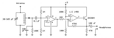
I am trying to understand the purpose of a couple of components in a schematic I am looking in at:

enter image description here

My questions are:

1) What exactly is the 100k resistor attached to the diode doing?

2) Why is the output of the rightmost op-amp fed into a transistor? Could the audio signal not be pulled directly off the output of the op-amp?

Thank you for your responses.

\$\endgroup\$
3
  • \$\begingroup\$ Jonk provides a great description regarding Qes1 its an envelope detector en.wikipedia.org/wiki/Envelope_detector \$\endgroup\$
    – sstobbe
    Commented Jun 26, 2017 at 2:33
  • \$\begingroup\$ Op-amp driving headphones directly? Yes, through a 100uF capacitor (to remove DC), and perhaps a 47 ohm resistor in series too, to limit current peaks. A headphone of 32 ohm or 64 ohm is a fairly heavy load for a 1458 op-amp. \$\endgroup\$
    – glen_geek
    Commented Jun 26, 2017 at 15:18
  • \$\begingroup\$ For RF better sensitivity, use polarized diode and "parabolic" detection. \$\endgroup\$
    – Antonio51
    Commented Sep 18, 2021 at 13:35

3 Answers 3

4
\$\begingroup\$
  1. The \$100\:\textrm{k}\Omega\$ resistor is part of an RC filter (as well as a DC return path.) Together with the \$300\:\textrm{pF}\$ capacitor, its filtering purpose removes the RF that is still present in what passes through the diode detector (smoothing it out) while also leaving the relatively low frequency audio signal envelope undamaged. Take a look at the RC time constant. Also imagine that node without the resistor present -- all you see then are a couple of capacitors and a diode feeding it. It really needs a DC path added, as well.
  2. That last bit uses an emitter follower as a driver. It can source fine, but is dependent on the \$470\:\Omega\$ resistor to ground for pulling down and sinking current. I'd definitely arrange things differently.
\$\endgroup\$
2
  • \$\begingroup\$ I guess i don't have much of an intuition as to how this particular filter topology works. High frequency shorts to ground, while low frequency gets blocked by the cap? How does it compare to something like this? Could this also be used (with Vin being connected to the diode)? \$\endgroup\$
    – phi1123
    Commented Jun 26, 2017 at 2:36
  • \$\begingroup\$ @phi1123 Your link is shows a capacitor that also bypasses high frequencies. But in the AM radio case you need a DC path to ground. \$\endgroup\$
    – jonk
    Commented Jun 26, 2017 at 3:41
2
\$\begingroup\$

The diode, resistor and capacitor form the demodulator. The resistor discharges the capacitor charged by the diode hence (in conjunction with the 300pF cap) it sets a high frequency audio cutoff of \$f_m = \frac{1}{2\pi R C }\$ or about 5.5kHz. It filters out virtually all of the carrier frequency since the carrier frequency of AM radio is >> 5.5kHz.

The output transistor is supposed to boost the op-amp output a bit- but with that 470 ohm resistor(!) I don't think it does much useful. The op-amp alone is capable of driving a modern sensitive headphone well enough.

Eg. a typical in-ear headphone has a sensitivity of 100-120dB SPL/mW (that's lots of volume) with an 18 ohm impedance. That means ~7mA is plenty, and the op-amp alone is fine since it can typically drive 20mA or so.

\$\endgroup\$
0
\$\begingroup\$

The diode is the demodulator stage. It rectifies the RF signal created across the tuned circuit, the rest of the op amplifiers are simply audio amplification.

The op amp does not have a high power output capability. The output transistor increases the current capability into the speaker/headphones. Typically you would use a 32 Ohm headset for a simple circuit like this, though the transistor may allow a small 8-16 Ohm speaker to work.

\$\endgroup\$
2
  • \$\begingroup\$ Thanks for your answer. I hadn't considered power output of the op-amp as an issue, so this makes sense. I understand the diode rectifies/demodulates the signal coming in from the tank circuit, I'm just confused as to what the 300 pF cap/100k res connected to the cathode are doing? Some sort of filtering? \$\endgroup\$
    – phi1123
    Commented Jun 26, 2017 at 2:13
  • \$\begingroup\$ Yes ....The diode is a half wave rectifier with 100k Ohm load, so the cap/resistor provide RF filtering (the rectified peak is the audio signal) while allowing the audio modulation to be presented to the first op-amp. \$\endgroup\$ Commented Jun 26, 2017 at 5:26

Your Answer

By clicking “Post Your Answer”, you agree to our terms of service and acknowledge you have read our privacy policy.

Not the answer you're looking for? Browse other questions tagged or ask your own question.