1
\$\begingroup\$

Greetings guys and gals,

I am seeing some odd behavior in my PIC-controlled circuit and need some help from the experts. I have a PIC18 at 3.3V turning on a bathroom vent fan via a relay.

The fan is the following model:

Panasonic FV-30VQ3
Current rating of the fan is 610mA @ 120VAC.

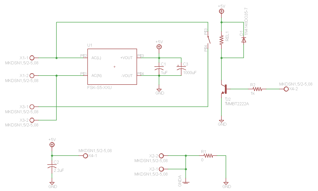
Schematic of my power/control attached.

U1: AC/DC converter VSK-S5-5UA (please excuse part number in schematic is obsolete)

U2: MMBT2222A to turn on the coil

REL1: PCN-D3M (TE Connectivity: 120VAC/3A, 25mA coil current)

R1: Connects PIC board GND to wall GND, but is not populated currently

The MKDSN's are 2-position terminal blocks:

X1: Input power from the power cord

X2: Connects fan and input GND

X3: Output power to fan

X4-1: Sends +5VDC to PIC board (other PIC board converts to +3.3VDC with linear regulator w/100uF ceramic cap at output)

X4-2: 3.3V logic from PIC that turns on relay

schematic

With no fan attached to X3 and the PIC cycling the relay on and off, the +5VDC, and subsequently 3.3VDC on the PIC board are stable. All is good here... no voltage drop, transient, or current flyback.

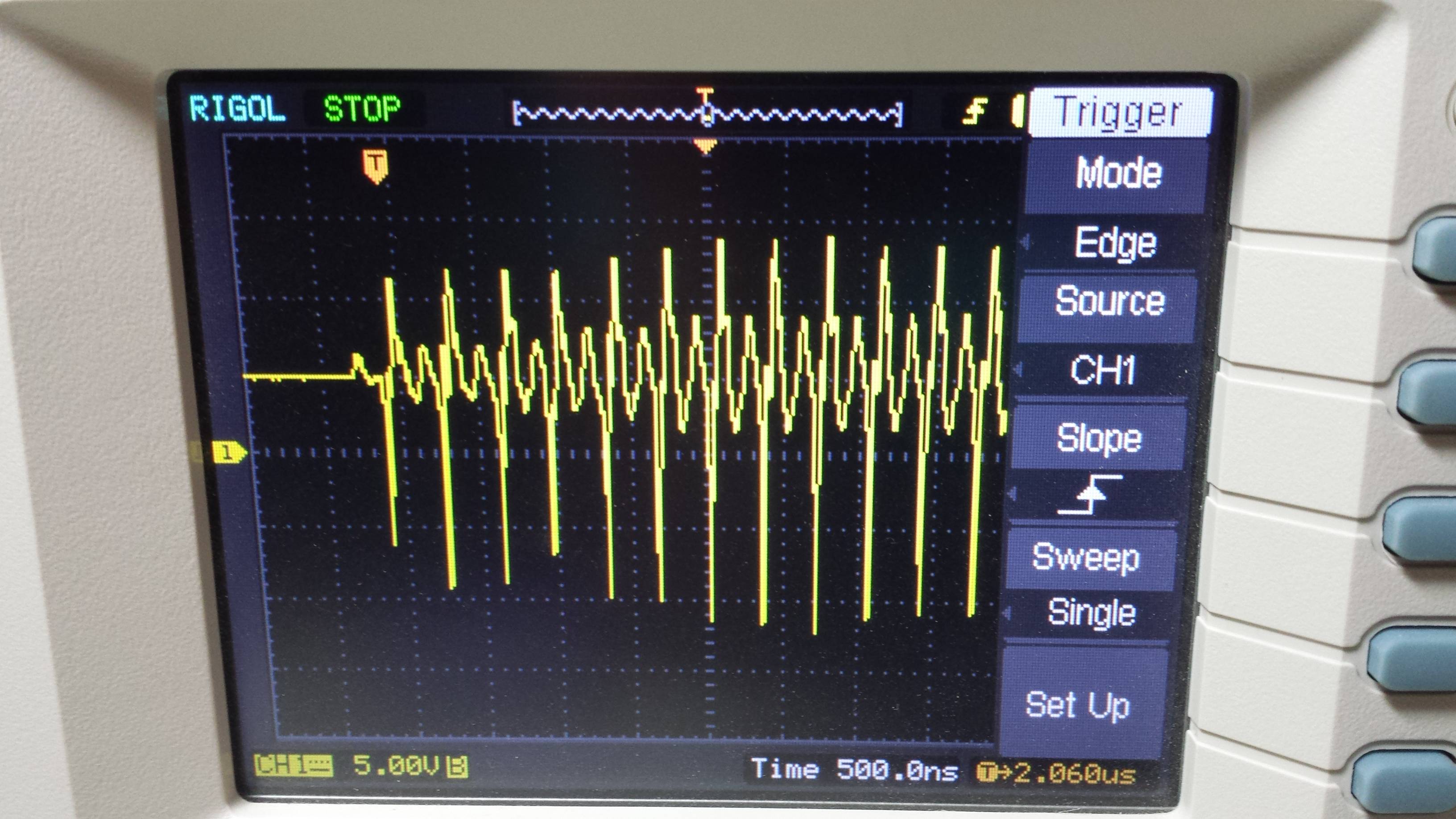
When I connect the fan to X3, I see the behavior that is shown in the attached screenshots of my oscilloscope. This is the +5VDC:

5V/div

Clearly the guts of the fan are to blame for the issue, but I would not think that the transients that I am seeing could exist with the amount of capacitance on the +5VDC node (C1 and C3).

The schematic provided on the sticker of the fan shows a capacitor on the white (line) of the fan itself.

Any ideas where this is coming from and how I can suppress this? The transient is causing my PIC to brown out and behave erratically, as one would expect when your operating voltage fluctuates so much.

Do I need more capacitance? Capacitor on the 120V of the fan? I mostly work with low power/voltage microcontrollers and FPGA's so 120V is not in my wheelhouse.

Any thoughts or input is appreciated. Thanks in advance, much appreciated.

\$\endgroup\$
5
  • \$\begingroup\$ That schematic has a lot of dead space that makes everything tiny and hard to read. Can you scootch things a bit closer together? \$\endgroup\$
    – AaronD
    Commented Jun 29, 2017 at 3:55
  • \$\begingroup\$ looks like measurement error with along ground wire instead of pin and barrel of prove. add a plastic line rated cap with a series R of about 10 Ohms to snub noise as relay fan turn off causes large back EMF noise. Twisted pairs helps as well as Ferrite CM choke. to relay and to fan. My bathroom fan timer switch causes EMI glitches to my video card in the next room too en.wikipedia.org/wiki/Snubber#RC_snubbers \$\endgroup\$
    – D.A.S.
    Commented Jun 29, 2017 at 3:56
  • \$\begingroup\$ Your schematic seems to show that the live and logic grounds are connected...? \$\endgroup\$
    – user133493
    Commented Jun 29, 2017 at 4:07
  • \$\begingroup\$ R1 is not populated, so the GND's are NOT connected. Updated the schematic to make it more legible. Thanks for the suggestions so far. \$\endgroup\$
    – Adam B.
    Commented Jun 29, 2017 at 4:17
  • \$\begingroup\$ Tony, are you saying add a snubber between X1-1 and X3-1? Thanks. \$\endgroup\$
    – Adam B.
    Commented Jun 29, 2017 at 4:23

1 Answer 1

1
\$\begingroup\$

It appears that your AC/DC converter cannot handle the high frequency spikes and passes them through. You need to eliminate them at the input to the converter (ps1, ps2). You need a small AC cap to bypass the noise to ground. I would start with a .01uf, 250v AC cap, right across the converter input pins, and see the resultant effect.
Make sure the fan cap is connected across the white and black wires, and the green wire to x2-1 and x2-2.

\$\endgroup\$
2
  • \$\begingroup\$ If the supply changes the output so much, it is surely broken? Please note that the (5V) output swings to almost ±20V (if I interpret the picture correctly). \$\endgroup\$
    – peter
    Commented Jun 30, 2017 at 11:08
  • \$\begingroup\$ Thank you for the information. I added a 0.1uF capacitor rated at 160V (all I had on hand) across the AC/DC input, as well as a 0.1uF/100ohm snubber across the relay switch and the transient persists. What doesn't make sense to me is how this is getting through all of that capacitance. According to my scope, the transient is oscillating at around 5MHz, which should be suppressed by either the input cap, snubber, output cap, or the 100uF ceramic cap at the output of the 3.3V linear regulator. How is this physically possible? Any ideas? Thanks. \$\endgroup\$
    – Adam B.
    Commented Jul 7, 2017 at 0:16

Your Answer

By clicking “Post Your Answer”, you agree to our terms of service and acknowledge you have read our privacy policy.

Not the answer you're looking for? Browse other questions tagged or ask your own question.