Greetings guys and gals,
I am seeing some odd behavior in my PIC-controlled circuit and need some help from the experts. I have a PIC18 at 3.3V turning on a bathroom vent fan via a relay.
The fan is the following model:
Panasonic FV-30VQ3
Current rating of the fan is 610mA @ 120VAC.
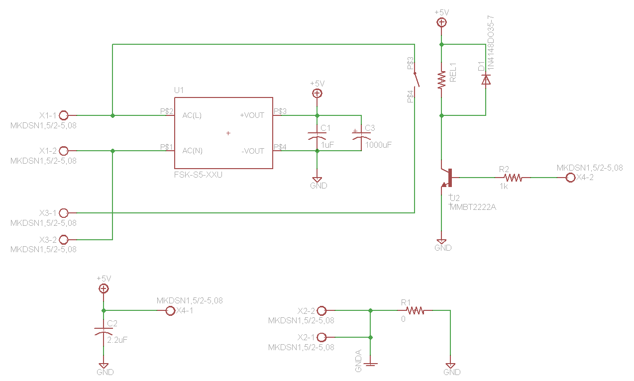
Schematic of my power/control attached.
U1: AC/DC converter VSK-S5-5UA (please excuse part number in schematic is obsolete)
U2: MMBT2222A to turn on the coil
REL1: PCN-D3M (TE Connectivity: 120VAC/3A, 25mA coil current)
R1: Connects PIC board GND to wall GND, but is not populated currently
The MKDSN's are 2-position terminal blocks:
X1: Input power from the power cord
X2: Connects fan and input GND
X3: Output power to fan
X4-1: Sends +5VDC to PIC board (other PIC board converts to +3.3VDC with linear regulator w/100uF ceramic cap at output)
X4-2: 3.3V logic from PIC that turns on relay
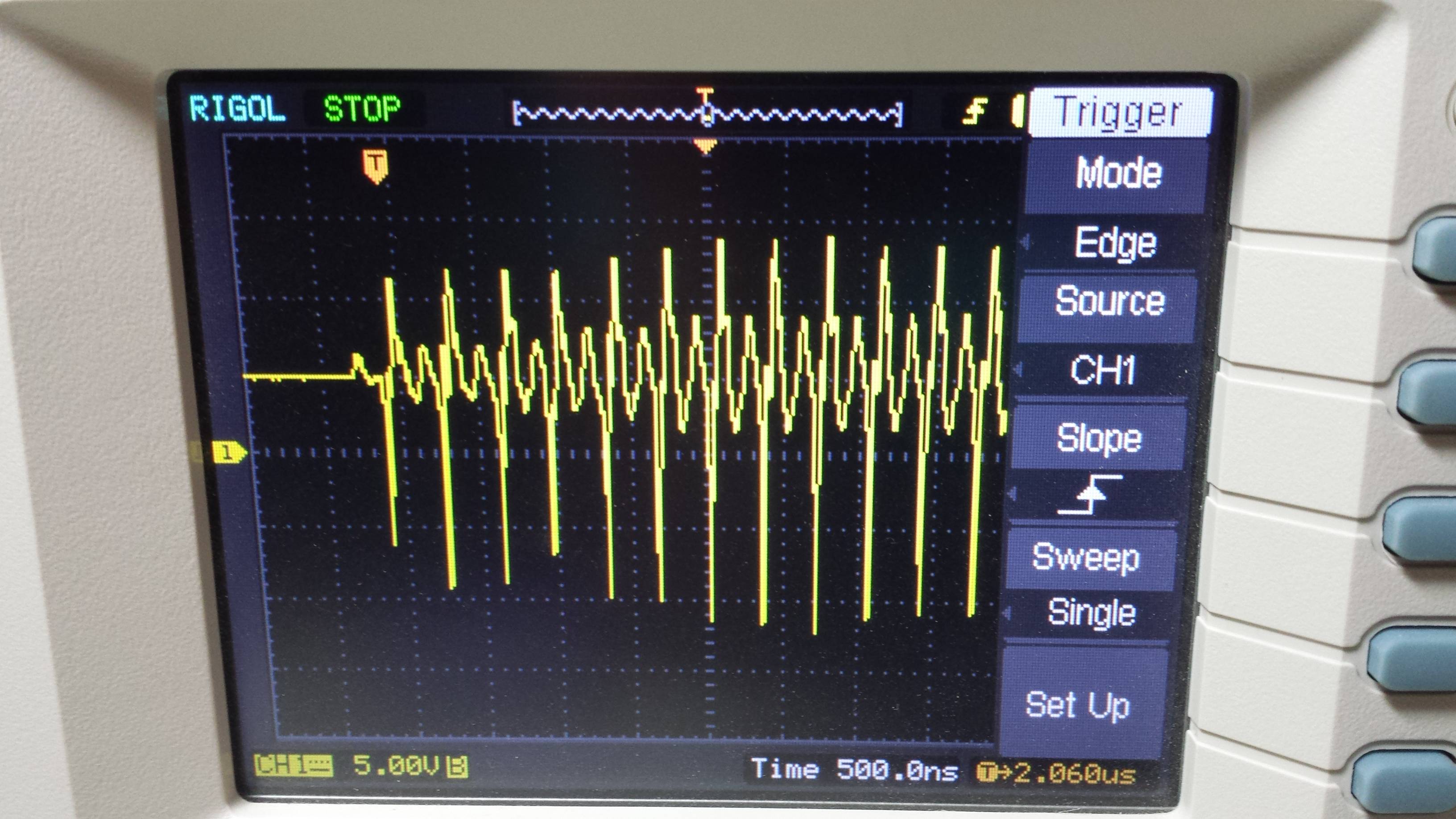
With no fan attached to X3 and the PIC cycling the relay on and off, the +5VDC, and subsequently 3.3VDC on the PIC board are stable. All is good here... no voltage drop, transient, or current flyback.
When I connect the fan to X3, I see the behavior that is shown in the attached screenshots of my oscilloscope. This is the +5VDC:
Clearly the guts of the fan are to blame for the issue, but I would not think that the transients that I am seeing could exist with the amount of capacitance on the +5VDC node (C1 and C3).
The schematic provided on the sticker of the fan shows a capacitor on the white (line) of the fan itself.
Any ideas where this is coming from and how I can suppress this? The transient is causing my PIC to brown out and behave erratically, as one would expect when your operating voltage fluctuates so much.
Do I need more capacitance? Capacitor on the 120V of the fan? I mostly work with low power/voltage microcontrollers and FPGA's so 120V is not in my wheelhouse.
Any thoughts or input is appreciated. Thanks in advance, much appreciated.


