4
\$\begingroup\$

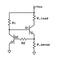
I am looking at this current limiting circuit on Wikipedia, which says that

The optional component R2 protects Q2 in the event of a short-circuited load.

Can someone explain why Q2 needs protection in this condition?

My understanding is that when Rload is shorted, the base of Q2 will see a voltage of Vcc, minus Vce of Q1 (because Q1 is in saturation, due to R1). Assuming that's above Vbe (of Q2), current will flow, but immediately cause Q2 to sink current from the base of Q1 - cutting it off.

Is the purpose of R2 to protect against this initial surge then?

Does R2 not affect the operation of the circuit? (As it forms a voltage divider with the base of Q2 - where the voltage is sensed) Or is it assumed that Q2 Ib is so small, that the voltage drop is negligible?

enter image description here

\$\endgroup\$
1
  • \$\begingroup\$ Don't neglect thermal requirements of this design, with Rload shorted fault current is, 0.7/Rsense, Power dissipation of Q1 is Pd = (Vcc-0.7)*(0.7/Rsense) \$\endgroup\$
    – sstobbe
    Commented Jul 25, 2017 at 1:57

5 Answers 5

2
\$\begingroup\$

Both of your thoughts are correct.

"Is the purpose of R2 to protect against this initial surge then?"

Yes. The base-emitter junction is essentially a diode, so without a current limiting resistor extremely large currents can flow (until failure.) It would basically short the Vcc supply to ground through the transistor. This is very likely to destroy Q2 before Q1 is choked off depending on the available current. At the least(or worst depending on how you look at it), it would be really bad for Q2 degrading its life leading to its failure later.

"Does R2 not affect the operation of the circuit?"

Yes. This is not a bad thing. If you are clever you can design the Rsense and R2 voltage divider to turn on when ever you want! Why would you do this? Well if Rload is variable it may be necessary to reduce the current to the load to keep Q1 within it's Safe Operating Area. This is a whole topic itself but basically, if you determine the max current allowed through Q1 you can design the voltage divider to begin choking Q1s base current at that point. This is called foldback protection and is very handy.

\$\endgroup\$
2
  • \$\begingroup\$ If Load current is 10 A and hFE was 100 each, what is max Ib2 ? 1mA so safe with R2=0 \$\endgroup\$
    – D.A.S.
    Commented Jul 24, 2017 at 22:55
  • \$\begingroup\$ I have got some great answers to this question, which I am grateful for! I think this one best addresses though the question as asked, as in why - whether necessary or not - R2 is present. \$\endgroup\$
    – sebf
    Commented Jul 25, 2017 at 21:50
2
\$\begingroup\$

I think that the purpose of R2 is to limit the current to the base of Q2, so that if the voltage developed across R_sense is significant that Q2 isn't damaged.

It's not that it's transitory, it is that it might exceed the rating of Q2, and that would result in Q2 failing, therefore never pulling down the base of Q1 to shut off the current. Consider that if you sized Q1 to carry a very large current (much more than the power supply could deliver) you could short R_load, and Q1 would be fine, but that might apply a relatively high voltage to the base of Q2.

If Q2 is chosen such that the base voltage can range up to Vcc (and not overdo the current limits of Q2), then you don't need the resistor. Otherwise R2 should be calculated to limit the current to the base of Q2 to a value that allows it to operate, but not exceeding the current limit for the base, or the resulting current limit through the emitter.

\$\endgroup\$
2
\$\begingroup\$

R2 * Ib2 lowers Vbe2 and thus raises current threshold a bit as a result.

I do not see any practical use for surge limiting, even if load is short circuited. Ib2= Iload/(Hfe1* Hfe2) max = peanuts... i.e. the current limiting protects itself. You need to compute Pd in each part. mainly Q1,R1,Re,load and size with 30% ~50% margin depending on ambient and max Tj=85'C for a good design.(opinion)

Drop R2.. as in 0 Ohms .....

Consider current of Q2 rated for 10% of Q1, and hFE=100, then Ib2 is 0.01% max of load current.

Normally, open loop gain of hFE1 * hFE2 = G = ( with hFE= 100 and G= 10k )I would choose a closed loop gain= R1/Re = √G and up depending on Vcc to limit Pd in R1. (tradeoff with regulation error)

Since R1 affects bias to Vbe2 it also affects current limit, reducing R1 current , reduces Ibe2 and thus raises threshold to load current limit.

With a 300:1 ratio regulation sensitivity with ΔIc/ΔVcc limit to about 1%. If this is results in excess Pd in R1 then compromise to 1000(R1):1(Re) ratio.

You can also complement everything and use PNP's with Load to gnd.

\$\endgroup\$
0
\$\begingroup\$

Yes it is to limit the current that goes into Q2 since in short circuit condition the voltage across R-Sense, and thus the current to Q2 could indeed rise too far on initial surge.

If R2 was too high you are also correct it would inhibit the operation, and thus it is chosen so as not to inhibit operation of the circuit, basically I agree with your conclusions.

\$\endgroup\$
0
\$\begingroup\$

Can someone explain why Q2 needs protection in this condition?

If the current through rsense is too high, AND q2 isn't diveting enough current away from q1 base, the voltage drop over q2 b-e junction will be too excessive.

It is a general ideal to put a base resistor there. But its value is limited.

\$\endgroup\$

Your Answer

By clicking “Post Your Answer”, you agree to our terms of service and acknowledge you have read our privacy policy.

Not the answer you're looking for? Browse other questions tagged or ask your own question.