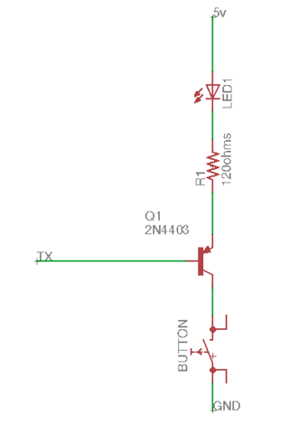
I am helping someone out over at aviation stack exchange -- they want a signal led for their gps receiver to do a preflight check to make sure it is working. They basically want to be able to press a button and see if the tx line is hot (as it should be) with a signal led. I suggested they use a transistor so as to not draw too much current from the tx line. Here is a link to the original post:
Here is a link to the datasheet of the PNP transistor i use: https://www.centralsemi.com/get_document.php?cmp=1&mergetype=pd&mergepath=pd&pdf_id=2N4402.PDF
And here is what I suggested. Is there anything in this circuit that would damage their equipment (or any mistakes I made in the circuit)?
Your GPS puck (GlobalSat BR355) runs on 5v and the UART line idles high (it is pulled high when there is no traffic). The first thing you need to do is find the power lines that go to the gps puck -- connect wires to these lines (5v and gnd) and run them to the spot where you want the button/led. Then make this circuit:
The value for R1 should be 120 ohms (which will yield a little under 20ma of current through the LED, assuming your led has a voltage drop of 2.1v (which the ones in the link I provided do have))
Just wire these components up according to the picture and solder them together -- I'll leave how to mount the switch and the LED up to you but make sure once you are done you cover all the exposed wire with glue and/or electrical tape and/or liquid electrical tape so they don't accidentally short out. Also make sure no exposed wires within the circuit are touching where they shouldn't touch (especially make sure you separate the pins of the transistor because if they accidentally touch the circuit will not work and you may damage your gps receiver -- long story short be careful in your wiring and make sure nothing is touching that shouldn't.
P.S. if you want you can move the button between 5v and LED1 if that makes it easier for you to mount; that would look something like this:


