1
\$\begingroup\$

I'm a hobbiest with litte resources for parts, so I'm short on things I can use.

Therefore I'm trying to rescue an old amplifier's case and use it for a different project. The potentiometer on the front has got me stuck though. It's a slider style, with some weird trickery.

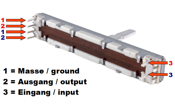
It has 6 pins. Four on the left, two on the right. Across the four on the right I get a linear taper but never much change in resistance. Across the far-apart pins (the ones coincidentally or not also in a parallel line geometrically speaking) give me a really weird audio-taper. The issue is: The frequency response is really low (cuts off high frequencies) and the sound isn't dimming how it's supposed to.

The pot changes resistance from 192k to 2.2 ish k. It never goes down fully. I'm not sure if I need to replace this with a linear taper (as I like Linear better for sound myself as a personal preference) or if someone can help me get this working correctly.

I read about the voltage divider stuff and I'm not sure how to implement that as I do not understand how this potentiometer works.

Either way, if I can replace the pot to a nicer newer one (although the old one is of a brand like Porsche is to cars and mitutoyo to measuring instruments) and get it working correctly. THIS has had me STUMBLED for SO long!

Edit: Thanks Transistor for your input! here's some of the things you requested.

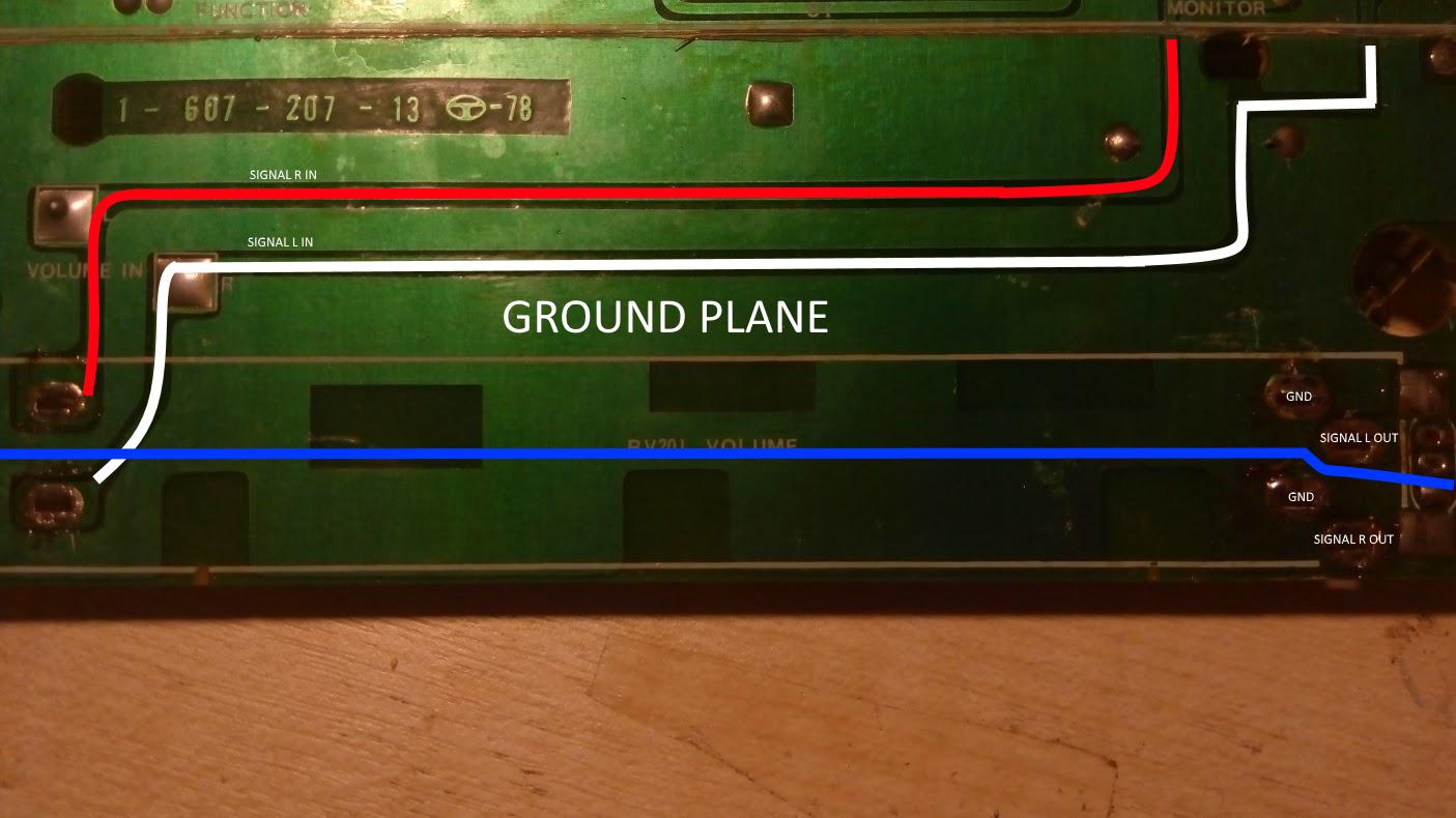
Original layout

Here you can see the original layout. I may just be seeing something over the head however. Note: Any measurements with probes ACROSS the blue line are NOT connected. The both sides of the blue line are seemingly two different potentiometers.

I will measure the resistances in the morning. It's a quarter to five here.

Oh and voltage divider: If I ground half the signal isn't that kinda like a small short circuit?

PS: If you'd like any more explanation on something specific or any pictures, feel free to let me know. I'm all about that helping.

\$\endgroup\$
1
  • 2
    \$\begingroup\$ Welcome to EE.SE. Yes we need pictures and, if possible, part numbers. Did you photograph the original wiring on the pots? Also, what was the function of the pot previously? Was it stereo? Number the pins on your photo and describe the measurement technique with reference to the numbers. \$\endgroup\$
    – Transistor
    Commented Aug 20, 2017 at 17:35

3 Answers 3

1
\$\begingroup\$

enter image description here

Figure 1. Dual slider pot.

schematic

simulate this circuit – Schematic created using CircuitLab

Figure 2. Standard wiring.

  • You should be able to measure the pot's resistance between 1 and 3.
  • Resistance between 1 and 2 should vary from zero when slider is towards 1 and maximum when slider is at 3.

Using linear taper on audio will result in nearly all the significant volume change occurring in the first 10% of travel. It's usually a terrible idea.

\$\endgroup\$
1
\$\begingroup\$

I wonder if you're measuring across the relevant pins. Maybe you need a "potentiometer primer":

A potentiometer in an analog audio amplifier will most certainly be a "stereo" pot, or dual-gang. Two separate wipers controlled by one shaft.

schematic

simulate this circuit – Schematic created using CircuitLab

Measuring between AR and BR should give the potentiometer's nominal resistance, and it should be roughly equal to the resistance between AL and BL. The resistance between AL-WL, WL-BL, AR-WR, and WR-BR will change.

You need to identify the relevant pins in your potentiometer.

If it was used as a volume control in an old amplifier, it may also have an extra segment and corresponding output called a loudness tap or similar. Since you only have 6 pins this should not be relevant, but you may have missed some non-obvious connections.

\$\endgroup\$
1
  • \$\begingroup\$ hey! I added some photos. Some info might indeed not be relevant but it's still useful and interesting to know. :) \$\endgroup\$ Commented Aug 21, 2017 at 4:10
0
\$\begingroup\$

I fixed it myself, somehow. I don't know how I did it, but I connected things back up again and it magically worked!

I still have some leakage current though, but that's most likely my fault..

Does anyone have some idea if these will fit on a perfboard? :)

\$\endgroup\$

Your Answer

By clicking “Post Your Answer”, you agree to our terms of service and acknowledge you have read our privacy policy.

Not the answer you're looking for? Browse other questions tagged or ask your own question.