To be clear:
- I don't have your PXF-20 that I might use to validate some assumptions I'm making. And its manual is somewhat "cloudy" to my reading of it.
- It seems as though your anemometer, from its datasheet, just as a fat, two-axis, four-pole magnet spinning inside a 4100 turn #40 coil to generate the AC.
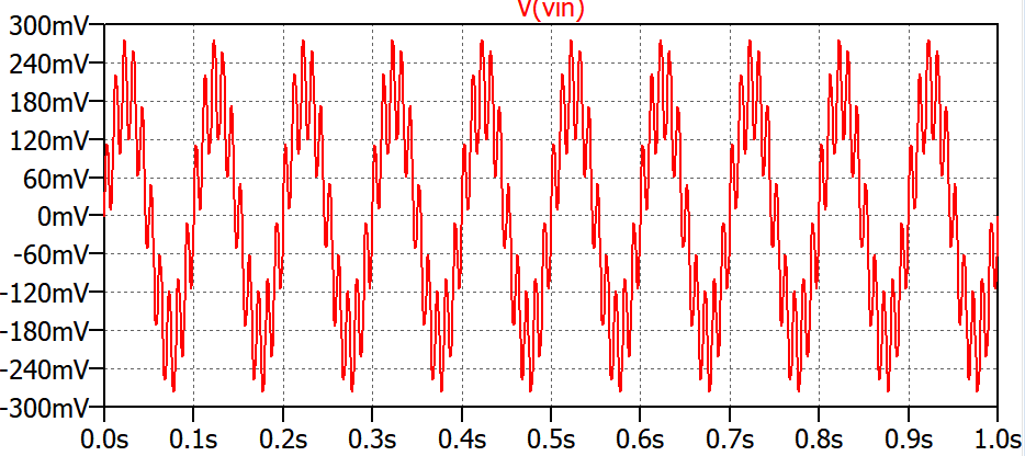
- The AC voltages are larger when the anemometer is spinning faster (as would be expected); at the slower rates this can be as little as \$80\:\textrm{mV}_\textrm{PP}\$; at the higher rates this can be over \$12\:\textrm{V}_\textrm{PP}\$.
- There's no indication in your writing (that I recall) which tells me that all you want to do is to hook up your anemometer to your PXF-20 so that it can output a nice, clean signal for you based only upon the frequency.
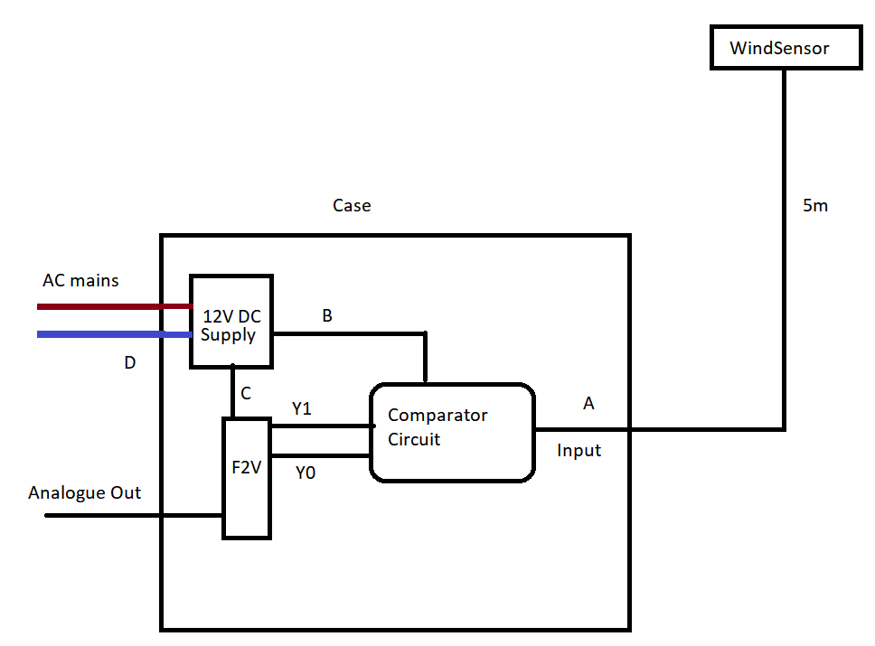
From these, I conclude that there is no particular reason to complicate what's needed by adding a separate power supply if it is possible to instead power the circuit directly from the PXF-20.
I think that's possible with a fairly simple circuit.
simulate this circuit – Schematic created using CircuitLab
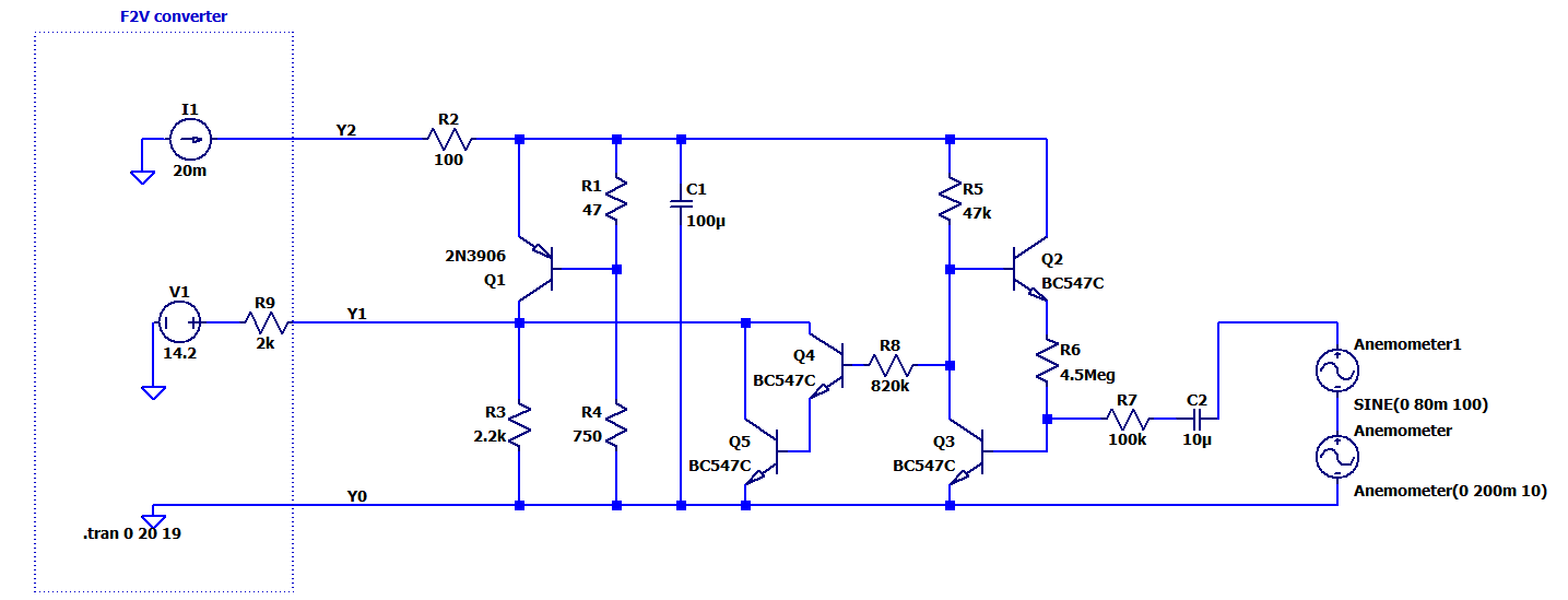
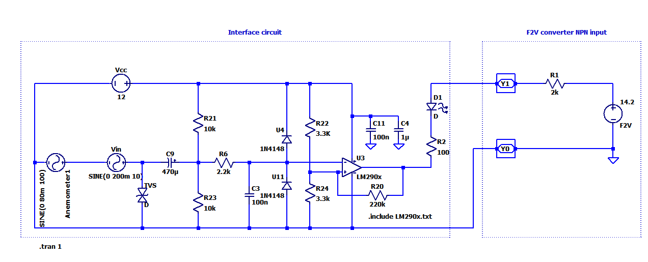
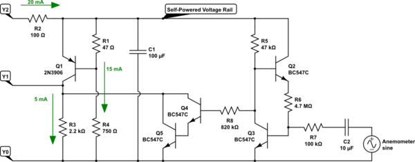
The left side, including \$R_1\$, \$R_2\$, \$R_3\$, \$R_4\$, \$Q_1\$, and \$C_1\$ play two important roles here. Using \$Y_2\$ and \$Y_0\$ they provide \$\approx 12\:\textrm{V}\$ power supply for the rest of the circuit (which requires only a very small amount of current to operate.) The exact voltage of this power supply isn't critical. These parts also provide an output to \$Y_1\$, which is specified in your datasheet as providing hysteresis (important) with a band sitting between \$5\:\textrm{V}\$ and \$7.5\:\textrm{V}\$. Without any input from your anemometer, \$Y_1\$ will be sitting at about \$1\:\textrm{V}\$, well below the threshold.
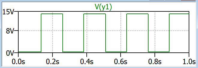
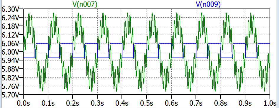
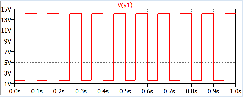
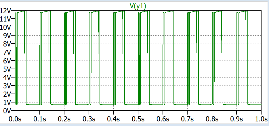
Now, the right side is powered and when the anemometer generates even a small signal the remaining circuit will alternately release and then drive the Darlington pair, \$Q_4\$ and \$Q_5\$, allowing \$Y_1\$ to rise well above the \$7.5\:\textrm{V}\$ threshold and fall well below the \$5\:\textrm{V}\$ as the small AC signal continues. This will work with even a small AC input, but it will also work with the higher generated voltages, too.
I've picked high-\$\beta\$ NPN transistors here and I think it's worth the trouble to use them. (I didn't include it, but you might also include a \$680\:\textrm{k}\Omega\$ resistor from the base of \$Q_4\$ to \$Y_0\$.)
There is no lightning protection here! Just be aware.
I've made some assumptions that are possibly unwarranted about your anemometer. If I had it here, I could do some testing on it. But I don't. I'm guessing that the wire resistance alone is at least \$300\:\Omega\$ in the wound coil. I honestly don't actually know, though. But I think the circuit is worth a shot.
If you do decide to try it, first just build up the portion that includes \$R_1\$, \$R_2\$, \$R_3\$, \$R_4\$, \$Q_1\$, and \$C_1\$. Then verify that there is something from about \$10\:\textrm{V}\$ to about \$12\:\textrm{V}\$ on the emitter of \$Q_1\$. You should also see about \$1\:\textrm{V}\$ less than that at \$Y_1\$. If that's working out about right, then you can consider adding the rest and seeing if that works okay.
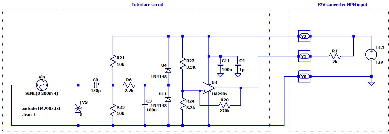
Mostly, this is to help you consider the idea of a self-powered circuit and show you one of the simpler (but less accurate) ways to approach solving that problem when interfacing an anemometer like this. It takes advantage of the provided current source and provides signal conditioning sufficient perhaps to drive the \$Y_1\$ input, as well.
I'm a little more worried about the slower anemometer speeds because of the tiny AC voltages generated. If that's still a problem more can be done, of course. You might try and change the value of \$R_6\$ a bit, one way or another, and see how that adjusts things better. But you'd probably need an oscilloscope tied to \$Y_1\$ and grounded at \$Y_0\$ to know better, then.
By the way, if you want to try and simulate your permanent magnet anemometer you might look over "Permanent Magnet Synchronous Machine Model for Real-Time Simulation" to see what I had to play with in trying to make sure the circuit I provided had a shot at working. I was able to get a behavior that relatively closely mimics the specifications provided by the anemometer datasheet, where merely changing the rate also changes the voltage approximately in the way they said it did. But it was annoying to develop and it's non-trivial. But it gave me a little better confidence that the circuit might work well, too. Worth a moment's trouble.
