1
\$\begingroup\$

I am trying to correctly implement a circuit context for the e2v MiCS line of gas sensors (for example MiCS-5525). Reading the FAQ from the manufacturer they make this statement:

HOW STABLE IS A SEMICONDUCTOR GAS SENSOR WITH TIME?

Above a certain operating temperature, the heater resistance will slowly increase with time. This is a known phenomenon that can be easily compensated with an appropriate circuitry. Long-term tests have shown that at 40 mW, no drift is measurable over 6000 hours. At 80 mW, the heater resistance can rise up to 30%. By powering the sensor with an appropriate series resistance on the heater, this resistance does not impact the sensor power by more than 2% over the same period, which is sufficient for most applications. More sophisticated “constant power” circuitry can be used to fully eliminate this effect.

I don't understand why a series resistor for the heater is necessary or would help at all to combat the phenomenon in question. For the MiCS-5525 would it not be sound to simply apply 2.4V from a voltage regulator across the heater terminals of the device? I also don't know quite understand what they are talking about when they suggest a "constant power" circuit as an alternative, how would one go about designing such a thing?

\$\endgroup\$

4 Answers 4

3
\$\begingroup\$

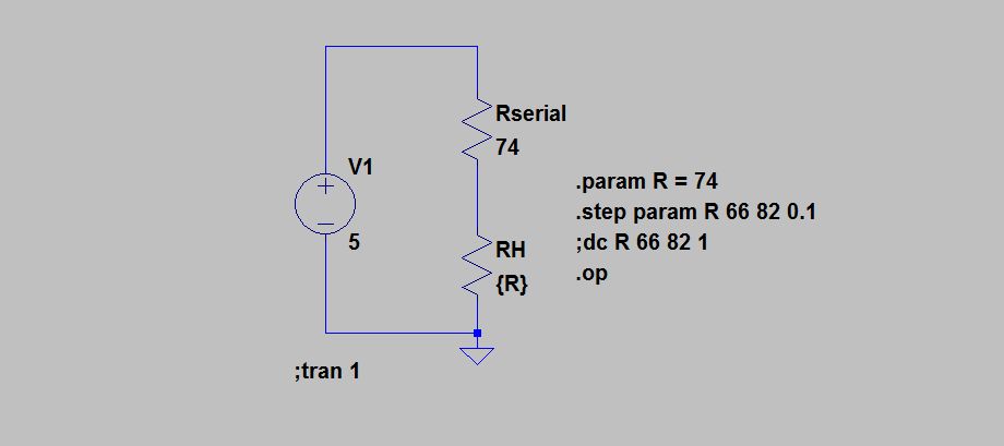
The following is an example application circuit to power the heater for the solid state gas sensor:

gas sensor heater circuit

,where V1 is our 5 V DC source, Rserial is a resistor, and RH is the heater on the gas sensor.

In this example we are using an Rserial value equal to our nominal powered heater resistance value. This means, by way of the maximum power transfer theorem, that most power will be transferred when the heater resistance is equal to the serial resistor, Rserial. If the heater resistance, Rh, varies in either direction from nominal the power dissipated in the heater will fall off quadratically.

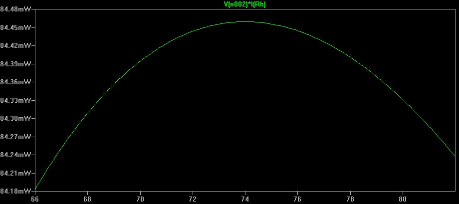
The following graph shows when the simulation is run. The X-axis is the Rh value being swept from its minimum to its maximum operating resistance value. The plotted curve is showing the power dissipated by the heater resistor Rh as its value deviates.

gas sensor heater circuit spice sweep

Notice that even if the heater value resistance changes on us by +- 15%, the power dissipated in the heater resistor changes by only ~1%, thus maintaining a relatively constant temperature on the sensing element.

Aren't solid state gas sensors fun!

Edit1: If your budget allows it and you are going to be required to become proficient with these technologies, I find that this book has a lot of useful information about the history, characterization and performance of solid state gas sensors. The circuit applications presented in the book, however, are lacking.

\$\endgroup\$
2
  • 1
    \$\begingroup\$ (solid state gas) sensors, or (solid state)(gas sensors)? ;-) \$\endgroup\$
    – stevenvh
    Commented Jun 2, 2012 at 10:24
  • \$\begingroup\$ Justin, wow this is some great stuff... thanks for taking the time to explain it! \$\endgroup\$
    – vicatcu
    Commented Jun 2, 2012 at 23:08
2
\$\begingroup\$

A key factor here is that heater resistor resistance varies between sensors and the application note is seeking to maintain constant heater power for all samples. Doing a numerical comparison of the effects of constant voltage versus series resistor feed produces a result that will surprise some.

The original app note and data sheet comments are probably not 'just wrong' but it's easy to miss their meaning.

Original data sheet gives ~= 76 mW heater power using a resistor from 5V.
BUT in the application note on page 2 under "How stable ..." it notes that the long term stability is improved by operating the heater at 40 mW.

Heater resistance is 75 ohms nominal but can be from 66 to 82 ohms.
This would need nominally 1.73 V at 75 ohms, but 1.81 V at 82 ohms or 1.56V at 61 ohms. (I specify Voltage to 2 decimal places which will not be achieved in practice.)

If you used a say 1.75V source you'd get 50, 41 and 37 mW at 61 / 75 / 82 ohms respectively - which is probably good enough.

BUT if you use a series resistor from a well regulated 5V supply, with 140 ohms you'd get heater resistor powers of 38, 41 & 42 mW with 61, 75 and 82 ohms heater resistance respectively. Which is probably very acceptable.

Using a series resistor gives MORE stable heater power than constant voltage as heater resistance changes.

A constant power circuit will maintain constant either I^2 x R or V^2/R or V x I for the heater resistor. This is not hard but requires an explicit or implicit multiplication or division in each case, while use of a series R seems to work "well enough".


ADDED

It's been suggested that the datasheet max heater power of ~= 80 mW should be used and the app note recommended 40 mW be ignored. The object of running at full power is to get shortest possible response times.

There are several factors at work here.
The application note BY the makers of the device (AFAIR) specifically state that if you run the heater at max power that you get long term drift AND that if you run it at half power the ill effects are low but it is very stable long term.

The aspect of response time may be important depending on context and application BUT is essentially independent of the stability issue. Decisions must be made, but if I was doing this I'd be looking closely at running at 40 mW . I'd look at response times at 40 mW and ~= 80 mW and also see if the accuracy of the stability claim could be supported.

\$\endgroup\$
7
  • \$\begingroup\$ It wouldn't be terribly difficult to achieve 10mV regulation on the voltage source for such a low power rating. \$\endgroup\$
    – akohlsmith
    Commented Jun 2, 2012 at 5:02
  • \$\begingroup\$ ... so you think it's better to run the heater at 40mW suggested by the generic app note than the 76mW dictated by the device-specific datasheet? \$\endgroup\$
    – vicatcu
    Commented Jun 2, 2012 at 5:26
  • \$\begingroup\$ Actually, in the context of solid state gas sensors the biggest worry is in deviation of a heater or sensor resistance over time on one particular sensor. What is most important is keeping the powered sensor's sensing temperature as constant as possible over their relatively long lifetimes (5-10 years), even if the thin film heater's properties changes. Even by maintaining a constant temperature though, the MOS sensing elements are still known to drift with time. \$\endgroup\$
    – justing
    Commented Jun 2, 2012 at 5:29
  • \$\begingroup\$ No, you will want to make sure that the sensor heater, Rh is indeed running at the 76 mW that the datasheet states. This higher temperature is needed for the sensing element to react to the different gases with a relatively short time constant. \$\endgroup\$
    – justing
    Commented Jun 2, 2012 at 5:31
  • \$\begingroup\$ @justin - There are several factors at work here. The application note BY the makers of the device (AFAIR) specifically state that if you run the heater at max power that you get long term drift AND that if you run it at half power the ill effects are low but it is very stable long term. The aspect of response time may be important depending on context and application BUT is essentially independent of the stability issue. Decisions must be made, but I'd be looking closely at running at 40 mW . \$\endgroup\$
    – Russell McMahon
    Commented Jun 2, 2012 at 10:10
2
\$\begingroup\$

A constant voltage would give you a constant power if the resistance is constant as well. They explain the resistor is prone to thermal drifting. If you'd keep the voltage constant with increasing resistance, power dissipation would drop, and operating condition only allow for a 6.7% change.

justin shows how a series resistor will limit power changes with changing resistance. You can prove that the device's power is maximum if the series resistor has the same resistance as the heater, justin's graph shows a maximum at 74\$\Omega\$ for a 74\$\Omega\$ series resistor.

This doesn't guarantee that the resistance will remain constant, however. If it increases, say from 74\$\Omega\$ to 75\$\Omega\$ power will change from 77.838mW to 77.834mW. That's a difference of 3.5\$\mu\$W for a 1.4% change in resistance. That's not going to stop the drifting.

You could keep power constant by creating a control loop where you adjust the supply voltage (4.8V across sensor and series resistor) by measuring the currently dissipated power. An easy way is to use a small microcontroller which measures the series resistor's voltage using an ADC, then calculates the sensor's power as

\$ P = (V_+ - V_{SENSE}) \cdot \dfrac{V_{SENSE}}{R_{SENSE}} \$

and adjust \$V_+\$ to keep the power constant, observing the limits mentioned in the datasheet:

\$ V_+ = V_{SENSE} + \dfrac{77.8mW \cdot 74\Omega}{V_{SENSE}} = V_{SENSE} + \dfrac{5.76V^2}{V_{SENSE}} \$

For best regulation choose a series resistor with a low temperature coefficient.

\$\endgroup\$
2
  • \$\begingroup\$ What kind of regulator could I use to dynamically adjust V+ though...? \$\endgroup\$
    – vicatcu
    Commented Jun 2, 2012 at 22:53
  • \$\begingroup\$ The "regulator" is what Steven suggested and I mentioned - a device to measure one parameter and adjust the other to keep power constant. A bottom end microcontroller with an ADC is enough. BUT as my calculations showed and others, a series resistor from 5V will probably do very well. \$\endgroup\$
    – Russell McMahon
    Commented Jun 3, 2012 at 1:09
1
\$\begingroup\$

You are correct that simple constant voltage source will make thermal feedback with more accurate self regulation.

So the question is why docs say it helps. Perhaps it is cultural legacy. In auto industry, for example, part count and reiability is very important. Marketing can not require from customers to use 2.5v regulated voltage source nor power regulator. The most they can ask is extra resistor. It is affordable. And works in practice, violating theory.

P.S. I wonder why 6000 hours is a number. Is it theoretically longest possible car mileage, or interval between house fires ? Edit: scratch it. I misread the schematics, thinking source on right is heater. The resistor is in divider chain to allow reading of sensor. Or else there will be no reading.

Edit2: The citing in your question where they say about heater in series with extra resistor simply makes no sense. It is possibly from some failed study.

The const power source is somewhat uncommon, but required in for this device. It should regulate P=U*I. But everyone knows it already. As it is rarely used, the regulator should involve analog multiplier reading I and U, or microcontroller with ADCs, whichever designer prefers.

\$\endgroup\$
8
  • \$\begingroup\$ yes you need a series resistor with the sensing element to generate a sense voltage, but the quote above is also calling or a series resistance with heater resistance. \$\endgroup\$
    – vicatcu
    Commented Jun 2, 2012 at 2:50
  • \$\begingroup\$ Thank you. I finally understood the source of confusion. The paper should be simply ignored. I wil google it, to see where is it coming from. \$\endgroup\$
    – user924
    Commented Jun 2, 2012 at 2:54
  • \$\begingroup\$ I've linked the FAQ in the question if that helps as well... \$\endgroup\$
    – vicatcu
    Commented Jun 2, 2012 at 2:56
  • \$\begingroup\$ OK found it. The claim of 2% immunity in power variations is false. 30% resistance change in chain with 10x const resistor is 2-3% of total resistance change and 30% voltage change with undercompensation in DC. Power will fluctuate even worse if resistor is present. The researcher was simply wrong. \$\endgroup\$
    – user924
    Commented Jun 2, 2012 at 3:01
  • \$\begingroup\$ ok... so you think my idea to just use a fixed voltage regulator at 2.4V across the heating element then? I'm going to give some other people a chance to weigh in before accepting an answer \$\endgroup\$
    – vicatcu
    Commented Jun 2, 2012 at 3:15

Your Answer

By clicking “Post Your Answer”, you agree to our terms of service and acknowledge you have read our privacy policy.

Not the answer you're looking for? Browse other questions tagged or ask your own question.