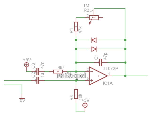
I've been looking at some distortion pedal schematics and many of them are a variation of the same circuit, such as these two:
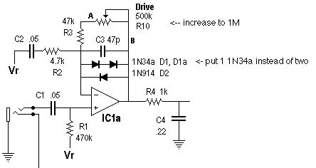
and
I know that most of these pedals are used with 9V batteries or power supplies, so a 4.5V bias is needed in the circuits, however whats the purpose of appliying the bias voltage to the C3 capacitor in the first image or C2 in the second image?, why not connect it directly to ground?, the capacitor would block any DC applied to it. I also know that the capacitor is probably there to achieve unity gain at DC, and a different gain for AC, but I still cant figure out why the DC voltage is applied there aswell.


