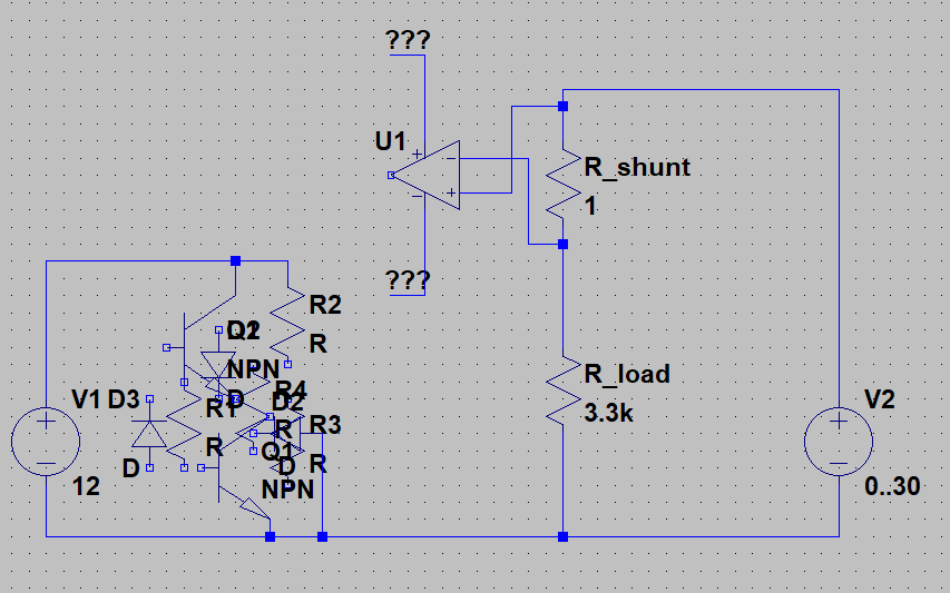
Just for context: The original problem I was originally trying to solve was measuring current through a shunt whose voltage potential may be outside the range of my control circuit's supply voltage.
Here, the control circuit on the left runs on 12 V DC, however the potential where I'm trying to measure may be in the range 0 .. 30 V DC. Even if I were to use an amp with rail-to-rail inputs I still wouldn't trust the circuit without any headroom, and also the load voltage (V2) might be less than the minimum supply voltage of the amp.
So first I thought measuring current with a shunt that is at a different potential than the control circuit must be extremely difficult, then I wondered how a multimeter even measures anything - well I suppose the battery doesn't care much what it's absolute potential is, even just connecting the ground of a 9V block to the node between R_shunt and R_load probably would have been enough. But I don't want a battery there, so I thought about how I could somehow move voltage from the control circuit on top of the load circuit.
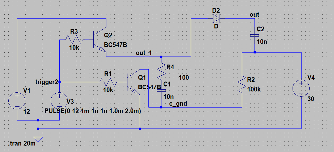
Regardless of whether the original problem could be solved in a better way, I decided to try this approach for educational reasons. By chance, I read in the datasheet of some power H-bridge IC that it uses a charge pump to drive the high side MOSFETs of the H-bridge because it has a similar problem. The charge pump inspired this kind-of DC-DC-converter-like thing:
- V1: Always 12VDC, used to charge the capacitor
- V2: 50% PWM pulse (0V .. 12V); periodically switches the transistors on. When high, the transistors connect the capacitor to the control circuit, where it will be charged.
- V4: Load supply (0 .. 30 V)
The idea is that we charge the capactior with the control circuit, and then cut all connections to the control circuit, somehow connect the ground of the capacitor to the target potential, and let it discharge. The unpleasant part is connecting it to the target potential, which is done with a 100k resistor. That means a small current flows from the load circuit to the control circuit while the capacitor is recharging in the control circuit, but it's enough to lift the potential when the control circuit is completely disconnected.
The thing is at this point I'm completely over my head. I haven't found any information on this arrangement (also I don't really know what to google for). From that I assume that other people may have done this before and decided that it's a terrible idea and I'm definitely going to shoot myself in the foot.
Is this a legitimate approach? If not, what is a viable alternative?


