There's no inherent danger to the op-amp, as long as its two inputs are never exposed to potentials that fall outside the range defined by its own its supply potentials at any given instant.
That's generally not a problem if the input signals come from sub-systems powered from the same supply rails, since they can't produce potentials outside of that range either.
Problems arise when there's a possibility to apply an input potential that lies outside the op-amp's supply range. For example, if at some given instant of time the supplies are +15V and -2V (the negative rail being slow to arrive at the full -5V), but somehow the source of op-amp input signal is trying to apply -4V to an op-amp input, then the input protection diodes of the op-amp will clamp the input to -2V, causing damaging levels of input current to flow. Here I've moved those protection diodes (boxed in blue) outside the op-amp to illustrate, with the current path shown in red:

simulate this circuit – Schematic created using CircuitLab
V3 here is a source of 4V negative with respect to ground, but if that source is powered from the same +15V and -2V supply, it will be unable to produce a voltage outside that range -2V to +15V, and the op-amp will be safe. However, if that source V3 has its own independent power supply (or comes from a completely separate system altogether) that settles faster than V1 and V2, then there's a possibility for this dangerous condition to exist.
For devices without input protection diodes, whether this condition is dangerous or not depends on the device itself, for which you must refer to its datasheet. In general, though, you should assume that devices won't survive.
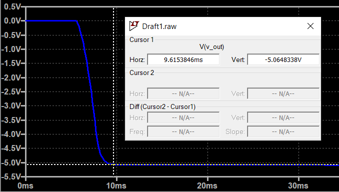
So the question is, is it possible for any op-amp (or other device) powered by your \$V_{OUT}\$ to have an applied input potential lower (more negative) than \$V_{OUT}\$ during the time it takes \$V_{OUT}\$ to reach and settle at -5V? If not, then you're good.
On a side note, if you're concerned that the negative supply takes an age to reach its target potential, then you should be equally concerned that the positive supply suffers the same lethargy, but for some reason you aren't concerned about that. I very much doubt that the positive supply is any better in this respect, but typically it only becomes an issue if external modules with independent supplies are applying signals with potentials outside the instantaneous supply potentials of the recipient.
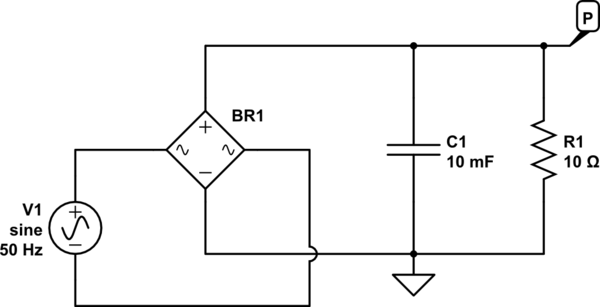
The positive supply, whether it's a DC-DC converter or a linear setup, will have a slow output rise too. Consider this linear design:

simulate this circuit
Here's the output \$V_P\$ rising slowly after AC power is applied:


