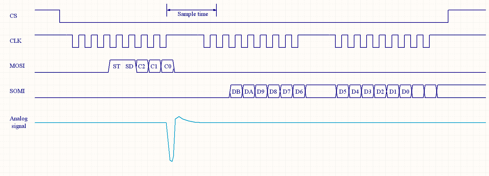
Many ADCs have capacitors on the input stages which are connected to an input when taking a measurement, and disconnected from the input when not taking a measurement. If the voltage on one of these caps does not happen to match the voltage on the input at the time that happens, current will flow into our out of the input pin as needed to charge or discharge that internal cap. This may or may not affect circuit behavior; there are four scenarios of interest:
- If the voltage on the cap happens to match the input voltage, no current will flow and there will be no problem.
- If the input pin is tightly coupled to a capacitor which is much larger than the chip's internal cap, the external cap voltage will not be appreciably disturbed by the brief current, and there will be no problem.
- If the input pin is connected via relatively low resistance to something that won't budge, such that any disturbance will be resolved between the time the capacitor is connected and the ADC takes its reading (that time interval is often called "ADC Acquisition Time, and on many chips is configurable), there will be no problem.
- If the above conditions don't apply, the voltage on the output pin may be disturbed when the chip connects its internal cap, and such disturbance will affect the measured value. Problem.
On many chips, if a reading has been taken recently, the voltage on the internal cap will match the voltage of the last reading, whichever channel it was taken on. Thus, if one takes two or more consecutive readings with the same channel, the effects of the capacitance on the reading will be relatively minor; taking a reading on another channel which is at a different voltage, however, may corrupt the first reading taken after the system is returned to the original channel.
On some chips, the voltage on the cap seems to be effectively random; regardless of the sequence in which readings are performed, the cap will sometimes add charge and sometimes remove charge, and taking consecutive readings on the same channel won't help. The only thing that will help is setting the ADC acquisition time long enough for the pin to settle.
If you have access to a scope, it may help make it possible to see whether inputs are being affected by these phenomena. It may not tell you everything you'd like to know (many scopes let one see signals within about 1%, and it's often desirable to take ADC readings that are more precise than that) but it should give some useful clues.

