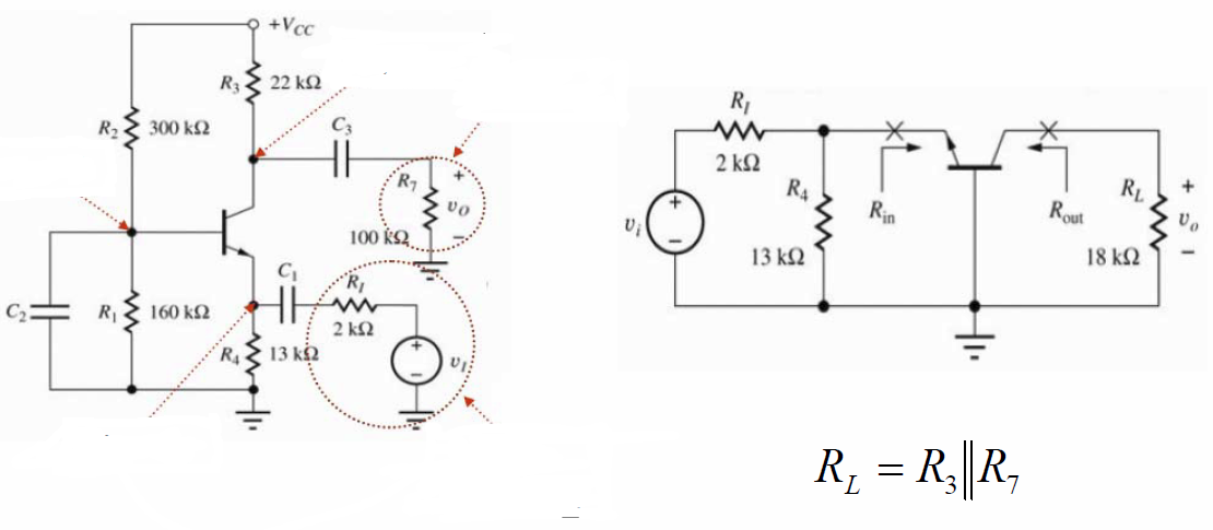
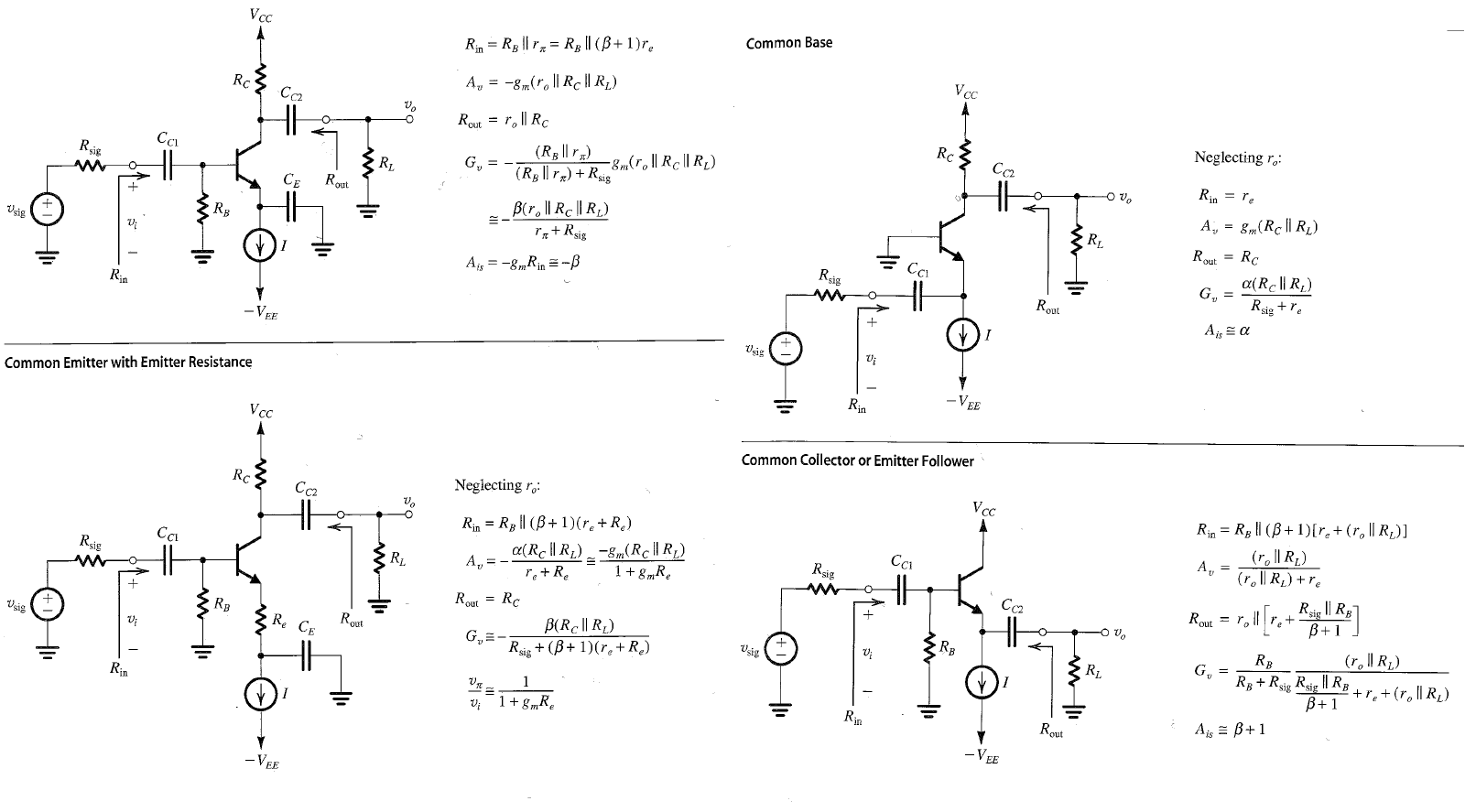
I'm studying the notes of my professor of electronics, and I'm noticing an inconsistency of \$R_{L}\:\$ compared to what I've seen around in books and on the web. Here's what is considered \$R_{L}\:\$ in those notes:

As you see, it's taking \$R_{L}\$ to be \$R_{3}\$ and \$R_{7}\$ in parallel. In my book, \$R_{L}\$ is meant to be what in this image specifically is \$R_{7}\$
My main issue rises when I try to calculate \$R_{out}\$, which is supposed to be calculated with
\$u_{in}=0\:\$, and
\$R_{L}=\infty\:\$, meaning \$R_{L}\$ is to be removed from the circuit to calculate \$R_{out}\$
Coming to this, I'm confused as to which \$R_{L}\$ I'm supposed to be using, or which one is the correct one to begin with.
For example, in the professor's notes \$R_{out}=r_{o}(1+g_{m}(r_{π}//R_{th}))\$, while in my book, a common base bjt has \$R_{out}=R_{C}=R_{3}\$.
Which one of the two ways is the correct one?

