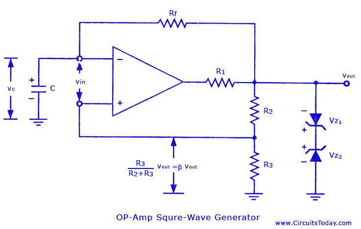
I have built myself a simple square wave generator with an operational amplifier and it works grea, but I want a second one with an inverted output.
\$\begingroup\$
\$\endgroup\$
4
-
2\$\begingroup\$ You haven't shown your supply voltages. Is it a symmetrical supply? e.g., +/- 12 V? \$\endgroup\$– TransistorCommented Dec 23, 2017 at 21:46
-
\$\begingroup\$ There are lots of HV logic gates called half and full-bridges. But your logic of using an Op Amp without specs, is premature. \$\endgroup\$– D.A.S.Commented Dec 23, 2017 at 22:14
-
1\$\begingroup\$ WHat does "How to invert a digital signal from operational amplifier" have to do with "Are there high voltage Logic OR gates ?" ? \$\endgroup\$– Trevor_GCommented Dec 23, 2017 at 23:59
-
\$\begingroup\$ Your over-complicating the wheel. Just add an op-amp inverter to the output of this one. Buy a dual op-amp and have both in the same 8 pin package...lol! \$\endgroup\$– user105652Commented Dec 25, 2017 at 1:59
Add a comment
|
1 Answer
\$\begingroup\$
\$\endgroup\$
5

simulate this circuit – Schematic created using CircuitLab
If it's a symmetrical supply (rather than single-ended) then just add an inverting stage after Vout on your circuit. The gain is given by \$ -\frac{R2}{R1} \$ which works out at -1 in this example.
-
\$\begingroup\$ The supply voltage is +15 and - 15V and on the output i have a square wave with an amplitude of 13V peak to peak. I dont know how to invert such a high voltage , im asuming to use transistors to make a crood OR gate \$\endgroup\$– SimeonCommented Dec 23, 2017 at 21:51
-
\$\begingroup\$ @Simeon, with respect to GND, what is the highest and lowest voltage of the output? You say it is 13V peak-to-peak, but you don't say what the high and low levels are, and this is important. \$\endgroup\$ Commented Dec 23, 2017 at 21:56
-
1\$\begingroup\$ @Simeon: Use an op-amp as suggested in my answer. \$\endgroup\$ Commented Dec 23, 2017 at 22:00
-
\$\begingroup\$ circuitlab.com/editor/#?id=9x9x4rnz8224 sorry forgot to mention there is a capacitor on the non inverting input 1u \$\endgroup\$– SimeonCommented Dec 23, 2017 at 22:03
-
\$\begingroup\$ Only registered users can see that link. If you are asking a question about a different circuit than the schematic you have posted then you are wasting everyone's time. Please fix your question. There's a CircuitLab button on the editor toolbar that adds an editable schematic into your question. Show supply rails and all component values and part numbers where appropriate. \$\endgroup\$ Commented Dec 23, 2017 at 22:07

