0
\$\begingroup\$

BS"D

Hi all.

I'm having trouble analysing the voltages/currents in various logic circuits.

For example, I can't understand WHY a NOT circuit actually works.

I've watched a YouTube video from Ben Eater (link: https://www.youtube.com/watch?v=sTu3LwpF6XI @ time 2:30)

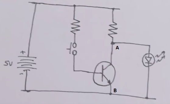
The circuits he presents there is attached here:

NOT gate circuit

Why is it that when you press the switch, no current flows through the LED?

As far as I'm concerned, pressing the switch equals to creating a short between points A and B. So I could replace the transistor with a wire that connects to A and B.

I don't see how these prevents current from flowing through the LED.

Using the equations for parallel loads, some current still flows through the LED.

He also says that when you press the switch, it zeros the potential difference between points A and B. I can't see how this happens using the equations I have.

Can someone please help and clarify?

Thanks! :)

\$\endgroup\$
1
  • \$\begingroup\$ BS"D Thanks for all the replies. I now see how it works :] \$\endgroup\$
    – Arye Segal
    Commented Jan 23, 2018 at 23:38

4 Answers 4

2
\$\begingroup\$

The description is simplified.

When you close the switch, if the resistor values are chosen appropriately, the NPN BJT will be saturated, so Vce will be reduced to some tens of mV typically.

With tens (or hundreds) of mV across the LED the current through the LED will be very, very small (but not quite zero) and thus no (perceived) visible light will be emitted.

\$\endgroup\$
4
  • \$\begingroup\$ Maybe change 'emitted' to 'perceived.' The LED will emit light at a visible wavelength, but the intensity will be imperceptibly low. \$\endgroup\$
    – vofa
    Commented Jan 23, 2018 at 17:59
  • \$\begingroup\$ @vofa Okay. Apparently < 10 pA is enough to get a bit of visible light. \$\endgroup\$ Commented Jan 23, 2018 at 18:07
  • \$\begingroup\$ @SpehroPefhany at 10mv, I calculate a current in the attoamps (using the schokley equation, which may not be accurate at low V) \$\endgroup\$
    – BeB00
    Commented Jan 23, 2018 at 19:08
  • 1
    \$\begingroup\$ @BeB00 I'm not necessarily convinced there is any light there at all, even at 100mV, but not interested enough to research it at the moment, hence the weasel wording. LEDs do appear to have a kind of defect-related threshold current that (in very old LEDs) was easily measurable. With modern LEDs it's now very small, but maybe still present. \$\endgroup\$ Commented Jan 23, 2018 at 19:19
2
\$\begingroup\$

Why is it that when you press the switch, no current flows through the LED?

Warning - severe analogy alert

When you flush the toilet it takes normally maybe 30 seconds to refill. However, if you have all the cold water taps on in the house (thus emptying water into their respective sinks and tubs), when you flush the toilet, it will now take several minutes to refill. It may never refill at all if the flow out of the taps exceeds the flow into the house.

So, you operate the switch and you turn the transistor on and it bypasses the current flow from the LED and returns it to ground/0 volts. The little bit of pressure (I mean voltage) left at the transistor collector won't be enough to pass current into the LED and it doesn't illuminate.

\$\endgroup\$
3
  • \$\begingroup\$ And also what you ate last night... \$\endgroup\$
    – Trevor_G
    Commented Jan 23, 2018 at 18:51
  • 1
    \$\begingroup\$ @Trevor_G That adds a whole new dimension to the answer. Maybe it just muddies the water too much hehe. \$\endgroup\$
    – Andy aka
    Commented Jan 23, 2018 at 19:06
  • \$\begingroup\$ They should add "severe analogy alert" as a subtitle to the whole forum. That and "May contain nuts!" :D \$\endgroup\$
    – Trevor_G
    Commented Jan 23, 2018 at 19:14
0
\$\begingroup\$

All transistors when used as a switch such as this are inverting voltage with respect to base input and collector output voltage. However normally when a switch is closed it is turning something on. Here it is the opposite.

Normally a series switch is used, but here it is a shunt switch. So Vce only has to be less the the forward voltage, Vf of the LED diode to turn it off. To make that happen Rb/Rc just has to be less the the current gain hFE. e.g. <100 but normally we operate a switch in saturation and hFE drops to 10~20 in this state.

\$\endgroup\$
0
\$\begingroup\$

I can see your confusion.

The issue with your attached circuit is is more in the understanding of the name than in the functionality.

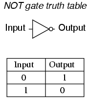
The circuit has an inversion function, in that a voltage greater than 0.6 at the base of the resistor will produce a low voltage at the collector. Conversely, a low voltage on the base will produce a high on the collector thanks to the pull-up.

enter image description here

Since that qualifies as meeting the truth table of a NOT gate it can be called a NOT function. All be it a really poor implementation.

The LED adds a little extra confusion to that, since it prohibits the output from going higher than the forward voltage of the LED, and being an analog device, never REALLY turns off. Without the LED the voltage on the collector is more "NOT-Gate" like.

Technically you can call it a NOT gate, but it really is better named just a transistor invertor.

\$\endgroup\$

Your Answer

By clicking “Post Your Answer”, you agree to our terms of service and acknowledge you have read our privacy policy.

Not the answer you're looking for? Browse other questions tagged or ask your own question.