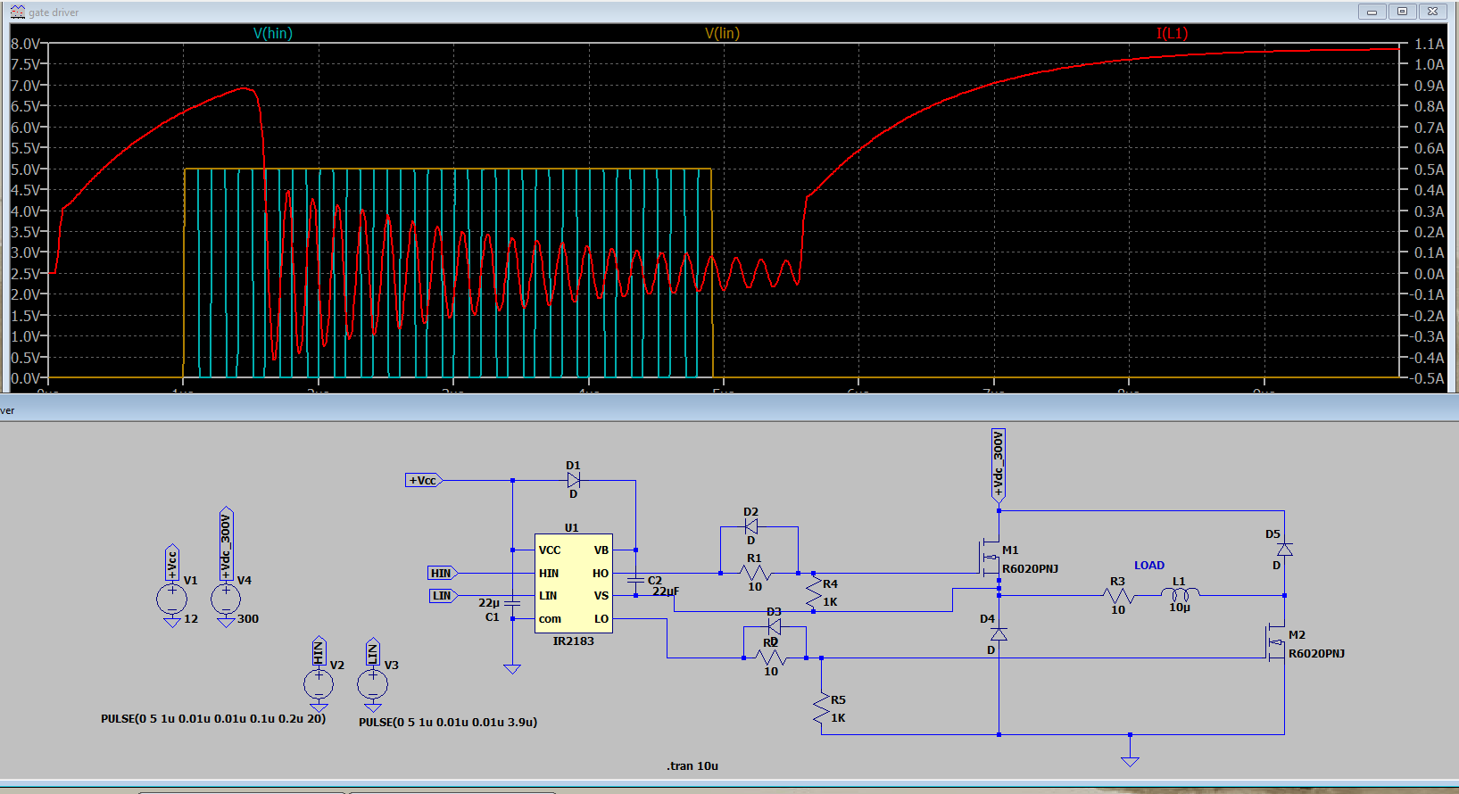
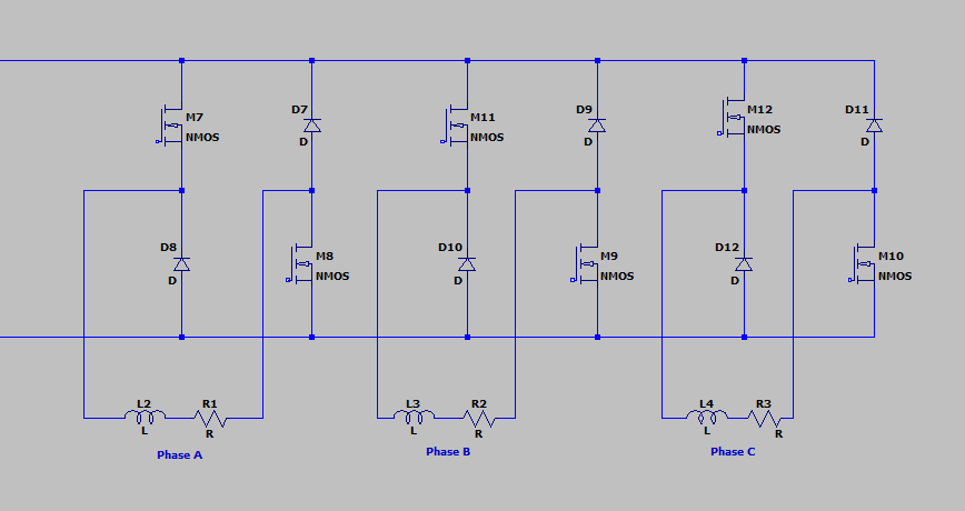
I'm designing power electronics for 3-phase 3 kW SR motor by using power MOSFETS of rating 600V. To drive the gates of these MOSFETS, I'm using IR2183 gate drivers, one per each phase.
The DC voltage at the drain of MOSFET is directly from the DC capacitor link which supplies 300 VDC.
Although the gate drivers should be in closed loop control system, for simulation purposes I’m using voltage sources for input pulses.
I have provided the circuit diagram and simulation results below. My question is, is this how the output current of an each phase looks like? And do I have to make any more changes to the circuit with higher inductance values (considering motor's inductance would be high)?
I would highly appreciate any suggestions provided.
Thanks in advance.


