0
\$\begingroup\$

New here and hoping you can help me out. I've been trying to work on a simple-ish PCB for a work project and need a hand. I'm trying to take one electrical input, and send it to 8 different outputs, once per charge, or once every n seconds. So it would follow one path, then once it is an open circuit, switch to the next and so on. Is such a thing possible?

The intended use is a pyrotechnics firing box. the idea is to take the firing wire (~3V charge,min 1.5V max 5V) and then send it to 1 - 8 firing locations. the firing program would send one firing signal and then after the pyro goes off, that particular firing location would not be a closed circuit anymore. If we did one that was timed it would be 4,6,8,10,15,or 20 secs(variable if possible) Working on getting the current numbers, will update with it shortly

Amps - 250mA min, 1A max

\$\endgroup\$
9
  • \$\begingroup\$ You mean like a cascade charger for cell phones? or the blow torch version for forklifts. The more measureable details, the better the answer \$\endgroup\$
    – D.A.S.
    Commented Feb 1, 2018 at 15:39
  • \$\begingroup\$ Welcome Wayne and, yes, it is but we need to know a lot lot more, edited into your question, not as comments please. Such as the application, the typical and max. current in and out per, the voltages, the typical time per output, if you want to vary it etc. The more detail you provide, the better the quality of the answers you'll attract. \$\endgroup\$
    – TonyM
    Commented Feb 1, 2018 at 15:39
  • \$\begingroup\$ You would have to be way more specific. 1.) What is electrical input, voltages, currents, AC/DC etc? 2. What does "once per charge" mean, 3.) what does "once it is open circuit" mean? \$\endgroup\$
    – Trevor_G
    Commented Feb 1, 2018 at 15:41
  • \$\begingroup\$ Pyro squids take energy to reach temp by kI²Rt approx. but if temp rises >2000'C then R rises by x10 then I drops with a constant V so it tends towards I*t * k factor like fuses \$\endgroup\$
    – D.A.S.
    Commented Feb 1, 2018 at 16:15
  • \$\begingroup\$ Only 8..thats a lot of work for just 8 fireworks. \$\endgroup\$
    – Trevor_G
    Commented Feb 1, 2018 at 16:22

4 Answers 4

1
\$\begingroup\$

enter image description here

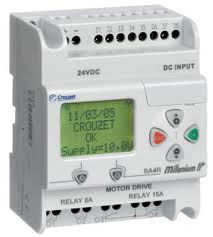
Figure 1. A typical micro-PLC (programmable logic controller). This one has four relay outputs but is expandable.

I would recommend a PLC for this task. They are robust, reliable, easy to program, available in AC or DC powered and with transistor or relay outputs. The micro varieties are made by Siemens, Allen-Bradley, Mitsubishi, Crouzet, and pretty much everyone else in the industrial automation game.

schematic

simulate this circuit – Schematic created using CircuitLab

Figure 2. Wiring scheme.

As always, with non-safety rated devices, design your circuit on the assumption that the outputs could switch on or off without warning due to malfunction or interference. This means adding a hard-wired switch in series with the supply for the outputs. I've shown series connection of two-poles of an emergency-stop button. Alternative arrangements include one contact in the positive and one in the negative.

You might decide on your choice of PLC by the availability of free programming software although most can be programmed via the front panel for simple programs.

\$\endgroup\$
0
\$\begingroup\$

I would say the simplest and safest would be a series of mechanical relays closed in sequence. Not solid state relays because some (all?) have leakage currents which might risk triggering your pyro. However what currents are we talking about?

\$\endgroup\$
0
\$\begingroup\$

Depending upon how much space you have can use use a high side FET to drive each channel ? Depending upon what your controller is (a micro ?) you could easily interface to a FET.

\$\endgroup\$
0
\$\begingroup\$

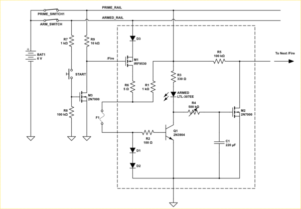
A chain of something like this might work.

schematic

simulate this circuit – Schematic created using CircuitLab

Initially low current flows through the igniter through R1 and sets up a voltage across D1 and D2 that biases Q1 on. Q1 then pulls the LED low and keeps M2 off. NOTE: I increased the battery to six volts to compensate for the diode drops.

When the gate of M1 is pulled low, it turns on and lets the full current flow through the igniter from the ARMED_RAIL. This current is expected to fuse the igniter.

When the ignoter fuses, Q1 will turn off allowing C1 to charge through the potentiometer R4. When it reaches the gate threshold voltage of M2 the latter will turn on pulling the gate of the next state low firing the next fuse.

R5 ensures the next gate is pulled high.

R6 limits the current to ~1A, and needs to be a power resistor, though it should not be on long.

Note the separate power lines. One applies power to the switches the other is a safety switch that prevents full power from ever being applied to the igniters. Use of a key-switch for that is prudent.

\$\endgroup\$

Not the answer you're looking for? Browse other questions tagged or ask your own question.