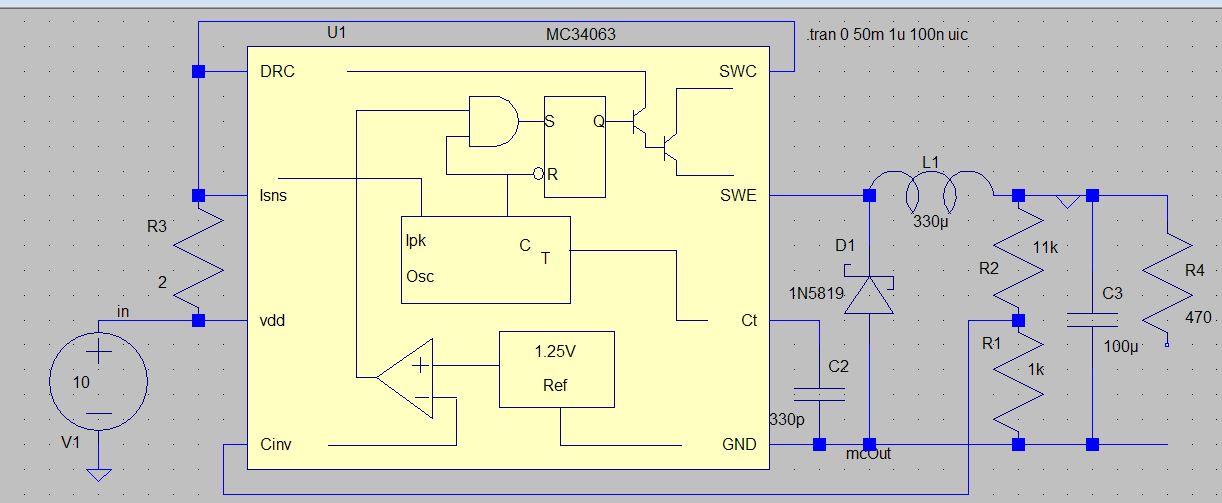
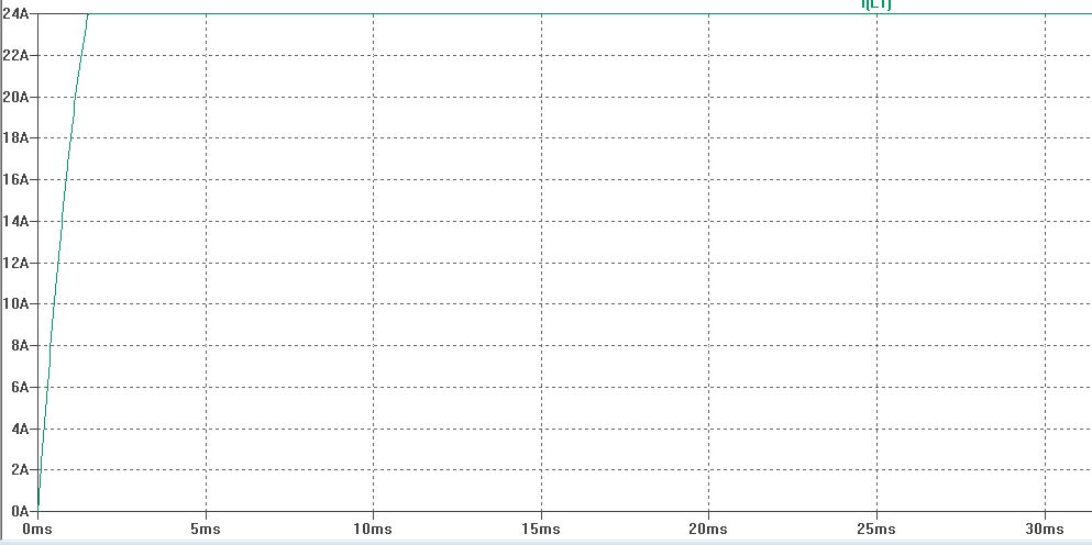
I fried a few MC34063 on the breadboard this evening.... was trying to make a 10V to -15V inverter to supply 30mA. It was working fine. However, the chips and inductor suddenly became hot when toggling the input power a few times. About 0.8A was flowing through the inductor when the chip failed. I thought the inductor core saturated, but simulations are also giving the same result if I lower the switching current. A similar circuit is below (actually I used 1mH 3.5Ohm inductor and Rsc=0.63Ohm (1Ohm turned out to be actualy 0.63Ohm)). The circuit below works fine if R3=1Ohm, but becomes weird if R3=2Ohm. Current flows into Vdd and out through Isns in the simulation (have not checked this in the failed parts). (Also, my timing cap was 1nF, not 330pF, it was running at about 33KHz, but oscilloscope showed gaps between clusters of square waves).
I checked with and without load on the breadboard, as well as simulation. Same results... and a pile of black chips (It took me a while to figure out). The inductor is fine, even after heating a bit each time.
So, what's going on? I know that MC34063 is an old design and all that, but this is like walking on eggshells. Everything works... till some kid toggles the power switch a few times...
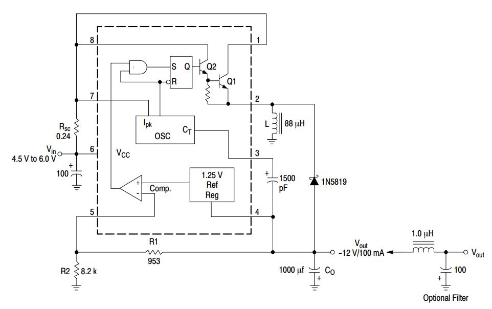
edit: Schottky diode orientation is fine. Here is the figure from datasheet, for reference

I agree with all comments about the breadboard. But, can anyone explain why the simulation fails if I decrease the current by increasing Rsc, or if I decrease the inductor value? I suspect the same thing happened on the breadboard. The inductance decreased enough so the darlington continued to conduct. Why did the current sense not work, even in simulation?
edit: I simulated while ramping up the voltage from 2 to 5 to 10V, every 10ms, and this one seems to simulate fine without the inductor current going up and locking (all other values same as the first schematic). May be the input cap is part of the design. Although, I did manage to fry one chip when switching off power to the circuit, can't figure out how that could have happened. I'll put in the input cap and try to fry another chip.
edit: I'm accepting analogsystemsfr's answer for pointing me towards capacitors. Initially I had a 330uF 25V on the output. I replaced it with 100uF 25V and added an input cap 100uF 25V as per the datasheet (100uF). All Capacitors were old but had tested OK on LCR meter before use. Both 100uF started heating up today, and I checked all three caps after that. All three caps had gone bad (but inductor and chip had not heated, and I was still getting my -15V output, althout very slowly after switch on). Replaced input and output caps with new 100uF 50V, and then input with 1000uF 50V. All are working fine with no heating, and tested OK after use. I toggled the power button maybe 40-50 times, and the chip did not fry. So I guess it was the capacitor. I still have no idea why it went bad. I have -15V across the caps, so it should have been fine, unless my input 10V got added to it somehow and became 25V across the caps during switching. Repetitive 25V across an old 25V cap may have damaged it... is my best guess now. And that shorted cap possibly led to chip failure. [My LCR meter shows two of the failed caps as a pair of opposing diodes with Vf of ~3V, the third one shows missing part (so failed open). None of the caps bulged or smoked.]


