0
\$\begingroup\$

enter image description here

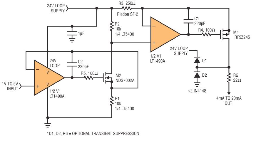
i test the below circuit using with LM358. and i use instead of n-MOSFET i use CL100 transistor and for p-MOSFET i use CK100.

in my 4-20mA converter circuit for 1.1 v input i get 31mA and for 4.4v i get 45mA as a output. this kind of situation what to do? to get a 4-20mA for my input... is that any components need to change

\$\endgroup\$
1
  • 1
    \$\begingroup\$ Bad choices in substitution \$\endgroup\$
    – D.A.S.
    Commented Mar 20, 2018 at 16:25

4 Answers 4

5
\$\begingroup\$

While the other answers address the inappropriate choice of op-amp, there is another significant problem.

instead of n-MOSFET i use CL100 transistor and for p-MOSFET i use CK100

You can't just do that and expect it to work. If you replace the FETs with BJTs, the op-amp outputs will inject extraneous currents to the signal path via the BJT bases. MOSFET gates are insulated, which is why they were chosen in the first place, as they don't suffer from this.

\$\endgroup\$
1
  • 2
    \$\begingroup\$ This is a bit of a red-herring. You can expect it to work reasonably with regular BJTs. Base current will be an error but not that big of a deal for most BJTs and it will only give a small percentage error. \$\endgroup\$
    – Andy aka
    Commented Mar 20, 2018 at 12:42
4
\$\begingroup\$

You substituted an inadequate op-amp- at 4mA the common mode voltage is within 1V of the positive rail.

Either use a better (and much more expensive) op-amp or redesign the circuit to work with an LM358.

Using those Indian BJT transistor types rather than MOSFETs will reduce the accuracy but it will probably still function, you should analyze the stability.

\$\endgroup\$
2
  • \$\begingroup\$ can you suggest any op-amp suit for my circuit.... \$\endgroup\$
    – Raji
    Commented Mar 20, 2018 at 11:19
  • \$\begingroup\$ LT1490.. Or use a parametric search for op-amps that can withstand 24V supply (preferably 36-44) and are rail-to-rail input and output. There a a number, but not a large number and they are all relatively expensive. \$\endgroup\$ Commented Mar 20, 2018 at 11:42
3
\$\begingroup\$

The LT1490A is specified as being: -

Rail-to-Rail Input and Output

The LM358 will not want its inputs to get as high as the circuit design expects. With 4 mA flowing through R3 the volt drop will be only 1 volt from the upper 24 volt rail. The LM358 is specified for an input voltage range of 0 volts to Vsupply - 1.5 volts.

Bad choice of op-amp.

The high output of the LM358 isn't be guaranteed to be better than Vsupply - 4 volts and this means that M1 will likely be permanently on.

\$\endgroup\$
2
\$\begingroup\$

When you copy an EDN design and make major substitutions with disregard to voltage and current swing , without reason, you get numerous faults.

Get the right parts or get back to Basics On the current sources or make wise choices on the substitutions.

https://www.edn.com/design/power-management/4371307/Convert-1-to-5V-signal-to-4-to-20-mA-output

From reading the comments, even the LT5400 is a marginal choice as well as lack of stability and short circuit protection.

Keep in mind this is the best way to learn but this example is far from production ready.

A better choice than LT5400 is MAX9620 and a better design used the DAC161S997. Or with discrete https://www.maximintegrated.com/en/app-notes/index.mvp/id/5610

\$\endgroup\$

Your Answer

By clicking “Post Your Answer”, you agree to our terms of service and acknowledge you have read our privacy policy.

Not the answer you're looking for? Browse other questions tagged or ask your own question.