I have ask this question in here before:Simulation is the same as my thinking,but different from the pape r(charging loop) ,and @a concerned citizen showed his\her simulation and schematic to me.However,everything,except the diode and switch,is the same as his ,but our simulation are different.By the way,his simulation is right,that is,the same as paper.
Our simulation are different,here are our difference:
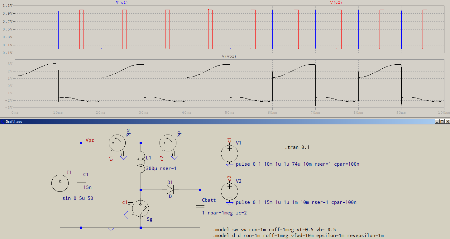
1.His positive half wave or negative half wave start from a positive or negative voltage,but mine start from 0V.
His schematic information and simulation
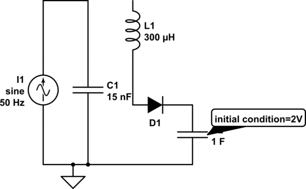
2.At the 0ms,his voltage is about 1.4V,and at this moment,all switch is opened,that is ,the equivelent circuit should be like this.And i think that is very strange,because at 0ms,the sine current source just ready to produce sine wave,and the capacitor,which initial condition is 2V ,did't connect that C1 with their positive pin ,why is there a 1.4V in the 0ms?

simulate this circuit – Schematic created using CircuitLab
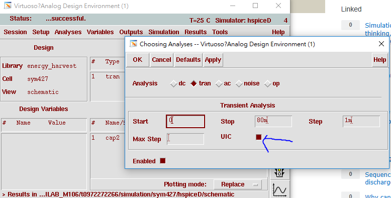
@a concerned citizen told me that You're probably using something similar to uic (initial conditions), I let the solver determine the .op. If I had used with uic, it would have, most likely, started from zero (everything).However,the simulation still start from 0V when i don't use the UIC.What is this mean by using .op?does anyone know that?


everything,except the diode and switch,is the same... not true, you are also using different software from @aconcernedcitizen \$\endgroup\$