1
\$\begingroup\$

back at it again trying to use your genius brains.

I have been trying to teach myself audio amplifier design. The big road block I am getting into is the control theory part of it, meaning how does the feedback loop affect the op-amp characteristics such as adding a Zobel network, or a capacitor compensation in the feedback.

I would love to understand and workout the math of how to model op-amp and understand how the poles and zeroes are.

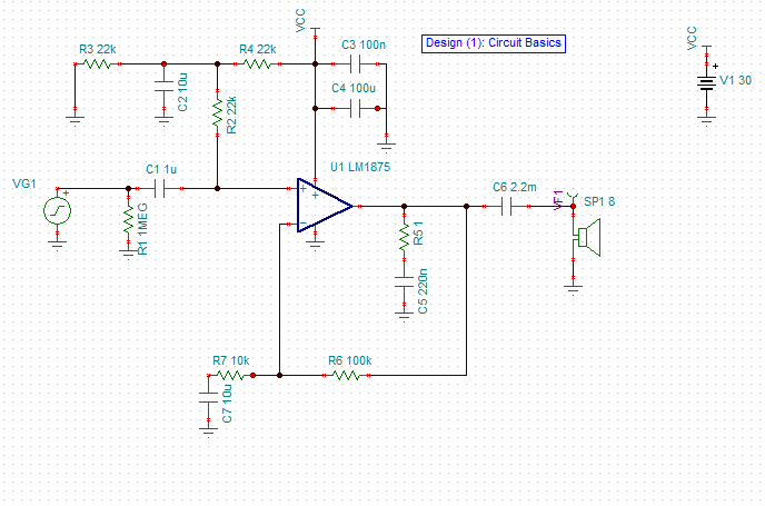
For example here is what I have been working with:

enter image description here

How do I approach this trying to figure out the feedback loop transfer function?

Do I assume in DC or AC? or do I need miller capacitance model.

My end goal is trying to figure out how does the Zobel network and other things affect the performance of the audio op amp. :)

Cheers.

\$\endgroup\$

1 Answer 1

1
\$\begingroup\$

This is not an op amp per se, rather it is an audio hi current 20 W power amp. It has an open loop gain of only 30 dB but a GBW of 5.5 MHz. That’s the bandwidth at unity gain is the GBW divided by the FB resister ratio gain. The example in the data sheet in figure 2 shows a gain of 20, thus it has a BW of ~ 275kHz. The speaker is partly inductive but if it has a passive crossover network it can become capacitive above 20kHz which will reduce the Amps phase margin towards oscillation at the x1 gain breakpoint f. Due the cross capacitive loading at high f , phase lag starts about 2 decades below the breakpoint. You have two options : use a high current 10uH coil wrapped around a 100 Ohm high power resistor or use a shunt RC network with a time constant of 1us such as 5 Ohms+ 0.22uF or 1 Ohm+1.0uF. This improves the phase margin above 1MHz by this lag/lead filter so that at 5.5MHz it won’t oscillate.

If you look at any RC filter you will see that phase shift in these low Q=1 filters takes +/2 decades about the breakpoint. In this case the 1 Ohm load being lower than the speaker will shunt any high f current away from the speaker

\$\endgroup\$
3
  • \$\begingroup\$ You're right its more so an audio amplifier. I am more of a mathematical guy so I appreciate what you're explaining but I had more of a different answer in mind, such as using root locus to see how the poles are influencing the system etc. Everything you are saying seems correct but I want to see the prove and the math behind it instead of taking your word for it. Thank you for the response, ill try to analyse what you said and translate it into math. \$\endgroup\$
    – Leoc
    Commented May 15, 2018 at 20:26
  • \$\begingroup\$ Look at the Bode plots with the snubbed filter in spec \$\endgroup\$
    – D.A.S.
    Commented May 15, 2018 at 20:37
  • \$\begingroup\$ I see, however I want to use math behind it, and perhaps design a lag-lead compensation for some reason \$\endgroup\$
    – Leoc
    Commented May 15, 2018 at 22:13

Your Answer

By clicking “Post Your Answer”, you agree to our terms of service and acknowledge you have read our privacy policy.

Not the answer you're looking for? Browse other questions tagged or ask your own question.